General
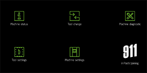
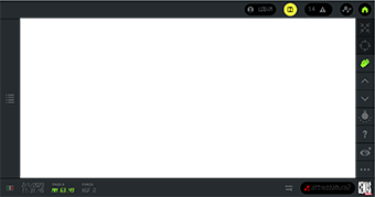
The operator interface on the welding machine, also known as the HMI or Touch Panel, is the device through which all control, configuration and display of machine/tool settings can be carried out. The operator interface consists of a touch screen monitor and software, developed by CEMAS Elettra s.r.l., which allows quick navigation within the panel and simple use of it by the operator. All the pages of the Operator Panel are divided into two areas: the internal area, where the icons that allow access to the different functions of the panel according to the specific function required are visible, and the external area, known as the frame, where the fixed icons are visible, i.e. the icons that are always visible and usable while navigating in the panel.
| INTERNAL AREA | FRAME |
|---|---|
 |
 |
Frame
Starting from the top-left corner and continuing clockwise, the following icons are present within the Operator Panel frame.
Bottom frame
The components located at the bottom of the HMI are listed below.
Language
The LANGUAGE shortcut key, represented by a flag icon, allows you to select the display language for the operator panel. Pressing the key opens the menu for selecting the desired language.
| LANGUAGE |
|---|
 |
| EXAMPLE LANGUAGE MENU |
| :--: |
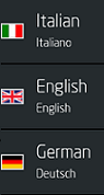 |
The languages that can be selected can be set on the MACHINE SETTINGS\LANGUAGE SELECTION page.
Date Time
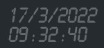
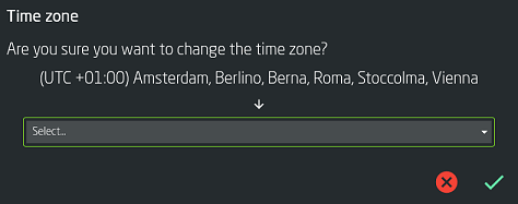
The DATE and TIME information is displayed to the side of the LANGUAGE button and shows the current date and time. Authorised users can change the machine’s time zone by selecting the button.
| DATE and TIME example |
|---|
 |
| TIME ZONE menu |
|---|
 |
Machine Information
The MACHINE INFORMATION section at the bottom of the screen allows you to view the status of the machine axes in real time, such as their current position and force.
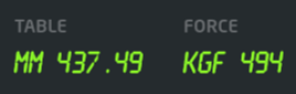
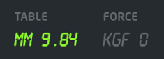
Here you can see the current position and force of the table. If the table is pushing against the head, the force value will be green.
| TABLE FORCE ON | TABLE FORCE OFF |
|---|---|
 |
 |
Tool Information
The EQUIPMENT INFORMATION section shows the code and name of the tool fitted to the welding machine.
The various statuses that can be displayed are shown below. If the tool has multiple cavities, the cavity currently in use is also displayed, indicated by LH or RH.
| No. | TOOL INFORMATION | DESCRIPTION |
|---|---|---|
| 1 | 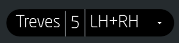 |
Tool present and recognised by the machine. In this condition, the tool is ready for use. (Example: NAME – Treves, CODE – 5, SIDE – LH+RH) |
| 2 | 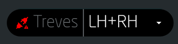 |
Tool recognised by the machine but not physically present. In this condition, the tool is disconnected and the text flashes. By selecting the item, you can start the tool removal procedure (see Message No. 4). |
| 3 |  |
Tool connected to the machine but not yet recognised. In this condition, you can select the item to start the tool recognition process (see Message No. 5). |
| 4 | 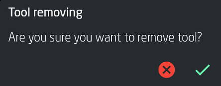 |
Pop-up displayed following a request to remove the tool. Confirm or cancel the operation using the appropriate buttons. If there are unsaved changes to the tool parameters, Message No. 5 will be displayed. |
| 5 | 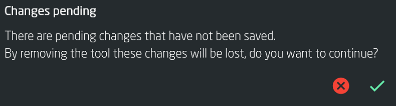 |
Pop-up displayed following a request to remove the tools when there are unsaved parameters. Confirm to discard the changes and proceed with removal, or cancel the operation. |
| 6 | 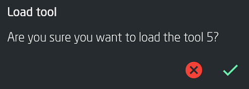 |
Pop-up displayed following a request to load the tool. Confirm to load the parameters into the machine (see Message No. 1), or cancel the operation. |
| 7 | No image | If the tool is completely absent, nothing is displayed in the tool information area. |
CEMAS Logo
The CEMAS LOGO hot key allows you to quickly return to the home page of the Operator Panel.
| CEMAS LOGO |
|---|
 |
Upper frame
The components located at the top of the HMI are listed below.
Configuration mode
The CONFIGURATION MODE button allows authorised users, i.e. tool configurators, to not save tool parameters and to work automatically at reduced speed. This working mode is useful for optimising machine working parameters.
| CONFIGURATION ON | CONFIGURATION OFF |
|---|---|
 |
 |
Save Changes
The SAVE CHANGES button, represented by a yellow button with a floppy disk icon, flashes when there are unsaved changes during tool configuration. By pressing the SAVE CHANGES button, the panel returns directly to the PRODUCT SELECTION page, where you can check the changes made and save them in the tool configuration.
From the same page, you can also cancel the changes made. This function can be useful during process optimisation tests, when you want to test different settings without keeping them permanently.
After saving or cancelling the changes, the SAVE CHANGES button disappears.
| CHANGES PENDING BUTTON |
|---|
 |
User
The USER field displays the name of the operator connected to the machine. If no operator is connected, the text login is displayed.
| USER field |
|---|
 |
Clicking on it brings up a pop-up window where you can enter your username, selecting it from the drop-down menu, and your password, typing it on the on-screen keyboard, to connect to the welding machine.
| Password pop-up |
|---|
 |
| ICON | ACTION |
|---|---|
 |
Cancel allows you to cancel the password entry. |
 |
Confirm allows you to confirm the password entry and connect the selected operator to the welding machine. |
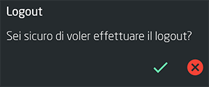
Clicking on the USER field with an operator connected brings up a pop-up that allows you to disconnect the operator.
| Disconnection pop-up |
|---|
 |
| ICON | ACTION |
|---|---|
 |
Confirm allows you to confirm and disconnect the operator from the welding machine. |
 |
Cancel allows you to cancel the operator disconnection. |
Alarms
The ALARMS key immediately signals if there is an error on the welding machine and allows you to quickly access the ALARMS MONITOR page. If alarms are activated, a number defining the number of active alarms appears to the left of the button.
| Alarms PRESENT | Alarms ABSENT |
|---|---|
 |
 |
Machine Status
The MACHINE STATUS shortcut key allows you to directly access the CONTROL PAGE, where you can view a summary of the current machine status. This function is particularly useful during the automatic cycle. The key lights up when the CONTROL PAGE is active.
| MACHINE STATUS ON | MACHINE STATUS OFF |
|---|---|
 |
 |
Home Page
The HOME PAGE hot key allows you to quickly go back to the home page of the Operator Panel. The button lights up when the HOME PAGE is opened.
| HOME PAGE ON | HOME PAGE OFF |
|---|---|
 |
 |
Right side frame
The components on the right-hand side of the HMI are listed below.
Home Position
The HOME POSITION shortcut key (identified by the icon with four arrows pointing towards a central point) allows you to reposition the machine to its base position, returning each mechanical part to its rest position. Reaching the HOME POSITION allows the machine to switch to automatic mode; if this position is not reached, automatic operation cannot be activated.
If this button is held down for a long time without any noticeable movement, alarms will be displayed at the end of the timeout period for the respective components, indicating the component that is preventing the base position from being reached.
The button is disabled when movements are not enabled.
| HOME POSITION ON | HOME POSITION OFF |
|---|---|
 |
 |
Automatic Cycle
The AUTOMATIC CYCLE button allows you to start the welding cycle in automatic mode. The cycle can only be started when the machine's safety devices are reset and the machine is in its basic position.
| AUTOMATIC CYCLE ON | AUTOMATIC CYCLE OFF |
|---|---|
 |
 |
Manual Cycle
The MANUAL CYCLE shortcut key allows the welding machine to be operated in manual mode, enabling the operator to perform all movements, including the welding cycle. When the key flashes, it indicates that the tool change mode is active; in this case, manual movements can only be performed from the TOOL CHANGE page.
| MANUAL CYCLE ON | MANUAL CYCLE OFF |
|---|---|
 |
 |
Up Arrow
The UP ARROW shortcut key allows you to move the table upwards when manual mode is active. The key is illuminated when the table is in its maximum position.
| UP ARROW ON | UP ARROW OFF |
|---|---|
 |
 |
The table can reach different positions depending on the status of the machine:
- Tool not present in the machine: the table will reach the maximum position allowed by the machine, limited between the maximum opening and the maximum stroke of the cylinder.
- Tool present in the machine: the table will reach the contact position, then perform the force between the table and the head. The maximum position of the table is determined by the TOOL HEIGHT parameter.
Down Arrow
The DOWN ARROW shortcut key allows you to move the table downwards when manual mode is active. The key is illuminated when the table is in the lowest possible position.
The table can reach different positions depending on the status of the machine:
- Tool not present in the machine: the table will reach the minimum position allowed by the machine.
- Tool present in the machine: the table will reach the loading position, corresponding to the base position.
| DOWN ARROW ON | DOWN ARROW OFF |
|---|---|
 |
 |
Lighting
The LIGHTING shortcut key allows you to turn the internal light of the welding machine on or off. If automatic mode is not active, the light will turn off automatically 1 hour after being turned on.
| Lighting ON | Lighting OFF |
|---|---|
 |
 |
Information
The INFORMATION key allows you to activate the information mode on the Operator Panel, namely, view the information menus of the various pages or keys, accessible using the INFORMATION icon specific to each one.
| INFORMATION ON | INFORMATION OFF |
|---|---|
 |
 |
Advanced Display
The ADVANCED DISPLAY button enables the more complex display of the Operator Panel, which allows more functions to be configured and displayed.
| ADVANCED DISPLAY ON | ADVANCED DISPLAY OFF |
|---|---|
 |
 |
Quick Actions
The QUICK ACTIONS MENU button provides access to a list of quick actions that simplify the use of the welding machine.
| QUICK ACTIONS MENU ON | QUICK ACTIONS MENU OFF |
|---|---|
 |
 |
Gate opening
The OPEN GATE shortcut key allows you to manually open the front gate of the welding machine. The key must be held down while the movement is being performed. The key is illuminated when the gate is in the open position.
| GATE OPEN ON | GATE OPEN OFF |
|---|---|
 |
 |
Gate closure
The GATE CLOSE shortcut key allows you to manually close the front gate of the welding machine. The key must be held down while the movement is being performed. The key is illuminated when the gate is in the closed position.
| GATE CLOSING ON | GATE OPENING OFF |
|---|---|
 |
 |
Buzzer
Option
The BUZZER shortcut key allows you to deactivate the alarm siren installed on the welding machine. The key is only visible if the signal column is installed and activated.
| BUZZER ON | BUZZER OFF |
|---|---|
 |
 |
Machine speed
The VELOCITY quick slider allows you to increase or decrease the speed of the machine's movements. Moving the cursor to the right (hare symbol) increases the speed, while moving it to the left (tortoise symbol) decreases the speed. The cursor affects every movement of the machine, both in manual and automatic mode.
The speed of the machine is limited when the "TEST CYCLE IN PROGRESS" mode is active, which is automatically activated following the modification of certain tool parameters, or when CONFIGURATION MODE is active. In both cases, a warning symbol is displayed, represented by a yellow triangle with an exclamation mark, to indicate the active condition.
| SPEED slider |
|---|
 |
| SPEED slider Limited |
| :--: |
 |
Menu Drawer
## DRAWER MENU
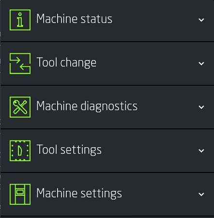
The DRAWER MENU allows you to navigate between the pages of the operator panel without having to return to the HOME PAGE. Press the button to display the menu.
| MENU DRAWER | MENU |
|---|---|
 |
 |
Internal Area
The Internal Area of the Operator Panel, i.e. the HOME PAGE, displays icons that provide access to the panel’s various functions. Clicking on each icon brings up a menu listing the pages that can be accessed to configure or view the functions of the welding machine and the tools.
| ICON | ACTION |
|---|---|
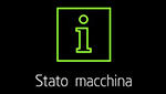 |
The MACHINE STATUS menu provides access to pages containing information on the machine’s status, such as the phases and status of the current welding cycle, any active alarms, the alarm history and the production history. |
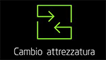 |
The TOOL CHANGE menu provides access to pages that allow you to perform tool change operations on the machine, in both automatic and manual modes, and to manage the data of the tools loaded onto the welding machine. |
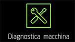 |
The MACHINE DIAGNOSTICS menu provides access to pages that allow you to: view the status of the PLC and motors, move the machine components and installed tools, perform tests, and consult the welding machine’s calibrations and certifications. |
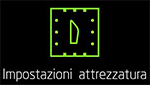 |
The EQUIPMENT SETTINGS menu provides access to pages where you can configure all functions relating to the tools installed on the machine, such as: axis positions, actuators, sensors, vacuum and welding. |
 |
The MACHINE SETTINGS menu provides access to pages where you can configure all functions relating to the welding machine, set access passwords and select the language. The functions accessible from these pages are primarily intended for CEMAS staff. |
 |
The machine’s LOGO on the HOME PAGE allows you to view the software licences. |
The following sections describe the various functions of the Operator Panel, organised into the main menus that make up the HOME PAGE.