Machine Diagnostics
The MACHINE DIAGNOSTICS menu provides access to pages where you can view the status of the machine and its components, operate the machine’s components and the tools installed, perform tests, and view the calibrations and certifications carried out on the welding machine.
PLC
The PLC page allows you to view and monitor the status of the individual inputs and outputs of the PLC and the cards installed on the welding machine. This function is particularly useful for maintenance staff when troubleshooting faults.
PLC hardware
The HARDWARE PLC tab allows you to view the hardware configuration of the PLC’s I/O module and check the status of the installed cards. The status of each I/O card can be seen immediately via an LED indicator located above the card: a green LED indicates that the card is functioning correctly; a red LED indicates that the card requires inspection by a maintenance technician. Possible causes of malfunction include: - Card not correctly seated in the I/O module slot. - Faulty socket (check by moving a working I/O card to another position). - Faulty or damaged card.
If a card is faulty or damaged, replace it with a new one of the same model.
PLC Configuration
The PLC hardware configuration can be defined via the Operator Panel, through the MACHINE SETTINGS menu, GENERAL SETTINGS page.
Warning
The PLC hardware configuration may only be changed by authorised operatorsDecoding Pin
The PIN DECODING card allows operators to view the connector pin mapping and their status. Each pin is represented by an LED indicator showing its status: grey = OFF, green = ON.
Each pin is assigned a binary weight (1, 2, 4, 8, 16, 32). The combination of pin states generates, via binary decoding, the code of the tools connected to the machine.
This page therefore has a diagnostic function, allowing you to: - Identify the pin address in the connector. - Check its status (ON/OFF). - View the tool code derived from the combination of signals.
24-pin
The 24-pin card is visible if a 24-pin socket is installed and enabled on the welding machine.
32-pin
The 32-pin card is displayed if a 32-pin socket is installed and enabled on the welding machine.
64-pin bus
The 64-pin BUS card is displayed if a 64-pin BUS socket is installed and enabled on the welding machine.
Signals
Option
The Signals card allows you to view the signals exchanged between the machine and external devices, which may include: - Remote buttons. - Audible or visual alerts. - Signals between the machine and smart accessories. - Signals exchanged for traceability management or robot control.
These signals are defined according to specific requirements and can only be configured by an authorised CEMAS configurator.
Motor status
The MOTOR STATUS page allows you to view information regarding the status of the drives installed on the welding machine.
Each drive has its own card, identified by the name shown in the top-left corner. By pressing the Info button (white “i” Icon) associated with each axis, you can view specific details of the corresponding hardware component.
For each motor, there is an LED labelled Referenced, which indicates that the axis encoder has been reset to the correct position during commissioning. If a motor is replaced, contact CEMAS to carry out the position reset procedure.
Table motor
The data sheet for the specific drive unit – i.e. the table’s electric motor – contains the following information.
Current
Current consumption, expressed in amperes (A).
Torque
Torque exerted, expressed in Nm
Force
Force exerted, expressed in kgf.
Load cell
Option
Force measured by the installed load cell, expressed in kilogram-force (kgf). The optional load cell allows for greater precision when adjusting the welding machine’s force.
Position
Position of the measured object, expressed in millimetres (mm).
Temperature
Temperature reached by the motor, expressed in °C.
Transducers
The absolute position of the measured object relative to the machine zero, expressed in millimetres (mm).
Mirror
The card of the specific drive, i.e. the mirror motor, contains the following information.
Temperature
Temperature reached by the motor, expressed in °C.
Current
Current consumption, expressed in amperes (A).
Torque
Torque exerted, expressed in Nm
Position
Position of the measured object, expressed in millimetres (mm).
Machine test
The MACHINE TEST page allows you to carry out a number of tests to test the proper functioning of the welding machine.
Warning
The MACHINE TEST activity can only be performed with the welder set to manual mode. The test may only be performed by CEMAS Elettra s.r.l. personnel and is aimed at testing the machine cycles.Force test
The FORCE test allows a force test of the welder to be performed. The test can only be performed after setting the machine to manual mode. To perform the test, it is necessary to move the welder table by means of the arrow keys located in the frame of the operator panel. Once the height has been reached to perform the force test, the actual force value at which the welder is working can be displayed in real time, thanks to the horizontal bar indicator shown on the panel.
Force
Actual thrust force reached during the FORCE test, expressed in kgf.
Dry Run Cycle
The DRY RUN CYCLE test enables the testing of the welding machine. The test is performed automatically by the machine, which will run repeated cycles as many times as set by the operator.
Enabled
Ticking the checkbox enables the welding machine testing function.
Skip welding
If the checkbox is ticked, the test cycle does not activate the vibration.
Repetition
Number of processing cycle repetitions, set by the operator, to be carried out to run the test. 250 processing cycles are usually set for hydraulic welding machines and 500 processing cycles for electric welding machines.
Delay
Time set by the operator that elapses between the end of a processing cycle and the next.
Assistance
The ASSISTANCE page contains the main welding machine data and general information on the work carried out by the machine until that moment.
Assistance Information
The indicated information is:
- TECHNOLOGY, i.e. welding technology used by the machine.
- MODEL, i.e. model of the welding machine
- SERIAL NUMBER, i.e. the serial number of the welding machine.
- RELEASE HMI, i.e. version of the HMI installed on the welding machine.
- RELEASE PLC, i.e. version of the PLC installed on the welding machine.
- WORKING HOURS, i.e. total working hours performed by the welder.
- TOTAL CYCLES, i.e. total cycles performed by the welding machine.
- PIECES PRODUCED, i.e. total number of good and reject parts produced by the welding machine.
- PLC SERIAL NUMBER, i.e. serial number of the PLC installed on the welding machine.
- MEMORY CARD SERIAL NUMBER, i.e. serial number of the memory card installed on the welding machine.
- DOCUMENTATION, i.e. QR codes and links that can be used to access the online documentation of the welding machine.
- EMAIL, which is a useful contact for requesting assistance from CEMAS Elettra s.r.l. Service.
Technology
Welding technology used by the machine.
Model
Welding machine model.
Remote assistance information
The indicated information is:
- MACHINE CONNECTED, namely machine remotely connected to CEMAS Elettra s.r.l. to perform support operations, if the LED is lit red.
- SUPPORT CONNECTED, namely CEMAS Elettra s.r.l. support operator logged on, if the LED is lit red.
| ICON | ACTION |
|---|---|
 |
When support is logged on, in addition to the red LED lighting up, the symbol shown in the top right corner of the screen appears. You can move the symbol to the four corners of the screen by clicking on it, as required. |
- DOCUMENTATION, i.e. QR codes and links that can be used to access the online documentation of the welding machine.
- EMAIL, which is a useful contact for requesting assistance from CEMAS Elettra s.r.l. Service.
Production date
Date of manufacture of the welding machine.
Serial number
Welding machine serial number.
HMI Release
Version of the HMI installed on the welding machine.
PLC Release
Version of the PLC installed on the welding machine.
Working hours
Total hours of work performed by the welding machine.
Total cycles
Total processing cycles performed by the welding machine.
Produced pieces
Total number of good and scrap pieces produced by the welding machine.
PLC serial number
Serial number of the PLC installed on the welding machine.
Memory Card serial number
Serial number of the memory card installed on the welding machine.
Remote assistance
In the REMOTE ASSISTANCE area, it is possible to view the connection status of the machine during a service intervention by CEMAS Elettra s.r.l. Service remotely and to download the documentation for the specific welding machine.
Machine connected
Machine remotely connected to CEMAS Elettra s.r.l. to perform support operations, if the LED is lit red.
Support connected
CEMAS Elettra s.r.l. support operator logged on, if the LED is lit red.
| ICON | ACTION |
|---|---|
|
When support is logged on, in addition to the red LED lighting up, the symbol shown in the top right corner of the screen appears. You can move the symbol to the four corners of the screen by clicking on it, as required. |
Documentation
QR code and links that can be used to access the online documentation of the welding machine.
Useful contact to request assistance from the CEMAS Elettra s.r.l. Service.
Manual movements
The MANUAL MOVEMENTS page makes it possible to activate the main machine movements in manual mode and the movements configured on the tool installed.
Tool manual movements
The TOOL card allows all objects configured on the installed tool to be displayed and used. The objects must be previously configured in the ACTUATORS AND PRESENCE page of the TOOL SETTINGS menu.
Presences
The presences area shows all presences configured in the PRESENCES card on the ACTUATORS AND PRESENCES page of the TOOL SETTINGS menu.
Each presence configured on the tool is assigned an object with the identification name assigned to the presence. The object contains a LED that can be on or off. If the LED is on, the presence is active.
Actuators
The actuators area shows all actuators configured in the ACTUATORS card on the ACTUATORS AND PRESENCE page of the TOOL SETTINGS menu.
Each actuator configured on the tool is assigned an object with the identification name assigned to the actuator. The object contains the keys work and rest, which allow moving the specific actuator. The keys must be kept pressed to bring the actuator to the work or rest position. If the key LED is lit green, the position is reached.
Vacuums
The vacuums area shows all the vacuums configured in the VACUUM card on the ACTUATORS AND PRESENCES page of the TOOL SETTINGS menu.
Each vacuum configured on the tool is assigned an object with the identification name assigned to the vacuum. The object contains the vacuum and blow keys, which allow activating the specific vacuum. The keys must be kept pressed to activate the vacuum or the blow. If the key LED is lit green, the vacuum or blow is active.
Machine manual movements
The MACHINE card allows the main movements of the machine to be operated in manual mode. Movements must be previously configured in the MACHINE SETTINGS menu.
Axes
The AXES card allows you to manoeuvre the main handling axes of the welding machine.
Table
The TABLE page allows you to move the welding machine’s table axis and displays a simplified diagram of the welding machine showing a simulation of the table’s movement.
Trolley position
Option
To load or unload tools from the welding machine safely, the table must be positioned at a specific height to allow the trolley carrying the tools to be correctly attached. The TROLLEY height can be adjusted directly on this page.
# Go in position
This allows you to position the axis at a specified height. The value entered is restricted by the limits defined in the MACHINE SETTINGS menu.
| Icon | ACTION |
|---|---|
 |
GO IN POSITION: the position is reached by holding down the button. The height is reached when the button lights up. |
Movement
| Icon | ACTION |
|---|---|
 |
The ARROW keys allow you to move the table up or down. The movement is performed by holding the key down. The destination elevation is shown above the arrow keys. |
Mirror
The MIRROR card allows to move the axis relating to the mirror on the welding machine.
Horizontal mirror movement
| Icon | ACTION |
|---|---|
 |
The ARROW keys allow you to move the mirror forwards or backwards. The movement is performed by holding the key down. The target elevation, relative to machine zero, is shown next to the keys. |
Gates
The GATES page allows you to operate the gates installed on the welding machine and displays a simplified diagram of the machine showing a simulation of the moving gate’s movement.
The OPEN and CLOSE buttons allow you to move the gate manually and must be held down to execute the movement.
If a two-hand control is installed on the welding machine, you must select the movement to be performed and start it using the physical START button.
Calibrations and certifications
The CALIBRATIONS AND CERTIFICATIONS page displays the calibrations and certifications carried out on the welding machine.
Calibration definition
Calibration means the use of a measurement standard to determine the relationship between the value displayed by the instrument and the real value. The reliability of a measuring instrument can be ensured by calibrating it to a measurement standard.
It is important to distinguish the concept of calibration from that of tuning:
- tuning is an operation to define the metrological characteristics of an instrument in order to define its accuracy;
- the purpose of calibration is to make the instrument more accurate and often, consequently, to improve its precision (particularly in direct reading instruments).
In other words, the former determines the current characteristics of the instrument, while the latter improves them. Calibrating the force that the welder table can impart enables extremely accurate machining cycles, as the force imparted is the best possible measurement.
Capability definition
The Statistical Process Control (SPC) consists of a set of statistical tests performed on a process (for example, a production line) or on an individual machine. Its objectives are:
- keeping the quality of the process under control;
- preventing errors;
- reducing costs due to problems encountered on non-compliant production units.
SPC techniques assess the variability of a process to identify the probability of non-conformity. The capability test is one of the checks that can be performed on a machine. The capability test considers two basic indices:
- Cm, or machine capability. It is the number of times that the machine dispersion is within the tolerance range. The higher its value, the better the machine. The Cm describes the repeatability of a machine with regard to the tolerance class, without considering its centring with respect to the nominal value.

- Cmk. The Cmk index, which links the machine capability to the centring around the nominal value, is used to study the centring of the machine capability with respect to the nominal value. A high Cmk indicates that the machine has a low dispersion and is well centred in the middle of the tolerance range.

A good Cm is essential for a machine. If the Cm is low, the only way to accept it without repairing it is to increase the tolerance interval.


If Cmk is low but Cm is high, the machine can be within specification parameters with a simple re-calibration.

Table
The TABLE card allows you to access the calibration, certification and capability cards relating to the force exerted by the lifting table of the welding machine.
Calibration
The CALIBRATION card displays the minimum and maximum forces calibrated and the result of the last force calibration carried out on the welding machine.
Minimum force
Minimum force that can be exerted by the lifting table in kgf, below which the welding machine could not work.
Maximum force
Maximum force that can be exerted by the lifting table in kgf, above which the welding machine could be damaged.
Calibration result
Result of the last calibration carried out on the welding machine and execution date of the calibration procedure.
Calibration graph
The GRAPH displays the entire calibration process. It shows the trend of the force exerted by the table (expressed in kgf) and the feedback of the plug of the considered axis (expressed as a %). These parameters are displayed with reference to the percentage force that the table can impart (expressed in %). Within the graph area, parameter curves can be displayed simultaneously or individually, using the VIEW button located at the base of each axis of the specific parameter.
| ICON | ACTION |
|---|---|
 |
VIEW ON button shows the curves on the graph. |
 |
VIEW OFF button hides the curves on the graph. |
By selecting a curve and dragging the cursor that appears, it is possible to display the parameter values precisely.
Certification
The CERTIFICATION card displays the minimum and maximum forces certified and the result of the last force certification carried out on the welding machine.
Minimum force
Minimum force that can be exerted by the lifting table in kgf, below which the welding machine could not work.
Maximum force
Maximum force that can be exerted by the lifting table in kgf, above which the welding machine could be damaged.
Certification result
Result of the last certification carried out on the welding machine and execution date of the certification procedure.
Certification graph
The GRAPH displays the entire certification process. It shows the trend of the force exerted by the table (expressed in kgf), the force setpoint (expressed in kgf) and the ideal curves that represent the reference ranges for the minimum and maximum forces. These parameters are displayed with reference to the control points set to perform the certification procedure.
Within the graph area, parameter curves can be displayed simultaneously or individually, using the VIEW button located at the base of each axis of the specific parameter.
| ICON | ACTION |
|---|---|
|
VIEW ON button shows the curves on the graph. |
|
VIEW OFF button hides the curves on the graph. |
By selecting a curve and dragging the cursor that appears, it is possible to display the parameter values precisely.
Capability
The CAPABILITY card displays the minimum and maximum forces certified, the Cmk corrective factor and the result of the last force repeatability test carried out on the welding machine.
Minimum force
Minimum force that can be exerted by the lifting table in kgf, below which the welding machine could not work.
Maximum force
Maximum force that can be exerted by the lifting table in kgf, above which the welding machine could be damaged.
Cmk
Corrective factor Cmk that ensures the repeatability of the force.
Capability result
Result of the last repeatability test carried out on the welding machine and execution date of the procedure.
Capability graph
The GRAPH displays the entire repeatability certification process. It shows the trend of the force exerted by the table (expressed in kgf), the force setpoint (expressed in kgf) and the minimum and maximum tolerance limits. These parameters are displayed with reference to the control points set to perform the certification procedure.
Within the graph area, parameter curves can be displayed simultaneously or individually, using the VIEW button located at the base of each axis of the specific parameter.
| ICON | ACTION |
|---|---|
|
VIEW ON button shows the curves on the graph. |
|
VIEW OFF button hides the curves on the graph. |
By selecting a curve and dragging the cursor that appears, it is possible to display the parameter values precisely.
Flatness
The PLANARITY card allows you to view the points detected to check the correct flatness of the table. The points are detected by a CEMAS Elettra s.r.l. operator using a comparator with respect to the welding machine head unit and after any adjustments. The values detected are considered compliant if they are within ± 0.05 mm of the reference point. The card also shows the result and date of the last detection.
Transducers
The TRANSDUCERS page displays the positions detected by the position transducers assembled on the welding machine.
Transducer diagram
The page shows a simplified diagram of the machine in which the transducers and the relative assembled sensors are highlighted. Each sensor bears on its side the measured position, expressed in mm.
| ICON | ACTION |
|---|---|
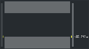 |
Single sensor. |
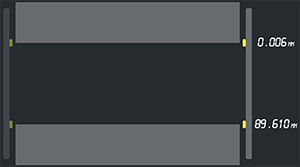 |
Double sensor. |
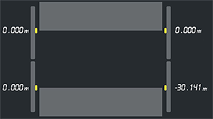 |
Dual sensor on 2 transducers. |
The correct configuration of the transducers installed on the welding machine must be set in MACHINE SETTINGS/GENERAL SETTINGS/COMPONENTS/TRANSDUCERS.
Position
Displays the difference between the lifting table position and the position read by the head transducer.
Table position
Displays the lifting table position with respect to the machine zero.
Head misalignment error
Displays the difference between the head position read by the right transducer and the head position read by the left transducer.
Table misalignment error
Displays the difference between the lifting table position read by the right transducer and the lifting table position read by the left transducer.