Alarms
This section describes the machine alarms, divided into two categories:
- Machine alarms, relating to the operation and components of the machine;
- Tool alarms, relating to the installed tools.
The purpose of the alarms is to alert the operator to any abnormal conditions or errors that may occur during system operation. For each alarm, the code, the message displayed, the description, the possible causes and the relative solutions are reported, complete with the procedures to be followed.
Alarms Tool
Below are details of the machine's tool alarms. The code, message and description are provided for each alarm. Each alarm also includes an explanation of the possible causes and related solutions, complete with the procedures to follow.
Actuator
...
M01000-0.XX - Pressure switch - No air present
The pressure switch positioned on the main line detects a pressure lower than the minimum pressure set. The default pressure setting is 5 bar.
No air in the system
Open the main air supply lever and check that there is actually air inside the tube.
Air-free regulator filter
Check that the regulator filter is working properly.
If it is faulty or malfunctioning, replace the component.
Electrically controlled coil
Check that the electric coil of the solenoid valve is working and controlled.
Further information
If the alarm occurs repeatedly or it is not resolved, contact the CEMAS Elettra assistance. The contact details can be found in MACHINE DIAGNOSTICS/ASSISTANCE.
T01000-0.XX - Actuator - Rest position timeout
The time within which the movement must be completed has been exceeded; therefore, the actuator has not reached the rest position.
Pneumatic control
Check that all pneumatic tubes are properly connected and that there are no obstructions.
Check the continuity of the air flow, ensuring that: - no tubes are bent - no tubes are damaged - all tubes are properly connected
Movement not completed
If the actuator does not complete the movement within the set time:
- check that the input set for the actuator is correct;
- check that the actuator stroke is not obstructed by mechanical impediments.
Sensors not working
Check the functionality of the sensors, ensuring that:
- the electrical contact has been inserted;
- the sensor cable has not been damaged;
- the sensor is correctly calibrated;
- the sensor is properly tightened.
If necessary, replace the faulty sensor.
Not enough time
The time set to perform the actuator movement is not sufficient to complete it.
If necessary, change the timeout time in TOOL SETTINGS/ACTUATORS AND PRESENCES/ACTUATORS.
Further information
If the alarm occurs repeatedly or it is not resolved, contact the CEMAS Elettra assistance. The contact details can be found in MACHINE DIAGNOSTICS/ASSISTANCE.
M01001-0.XX - Pressure switch - Safety inputs not present
At least one of the two sensors upstream of the pressure switch positioned on the main line does not detect sufficient pressure.
T01001-0.XX - Actuator - Work position timeout
The time within which the movement must be carried out has been exceeded; therefore, the actuator has not reached the work position.
Sensors not working
Check the functionality of the sensors, ensuring that:
- the electrical contact has been inserted;
- the sensor cable has not been damaged;
- the sensor is correctly calibrated;
- the sensor is properly tightened.
If necessary, replace the faulty sensor.
Movement not completed
If the actuator does not complete the movement within the set time:
- check that the input set for the actuator is correct;
- check that the actuator stroke is not obstructed by mechanical impediments.
Pneumatic control
Check that all pneumatic tubes are properly connected and that there are no obstructions.
Check the continuity of the air flow, ensuring that: - no tubes are bent - no tubes are damaged - all tubes are properly connected
Not enough time
The time set to perform the actuator movement is not sufficient to complete it.
If necessary, change the timeout time in TOOL SETTINGS/ACTUATORS AND PRESENCES/ACTUATORS.
Further information
If the alarm occurs repeatedly or it is not resolved, contact the CEMAS Elettra assistance. The contact details can be found in MACHINE DIAGNOSTICS/ASSISTANCE.
T01002-0.XX - Actuator - Rest position not released
The sensor detecting the rest position of the actuator continues to signal the position reached.
Pneumatic control
Check that all pneumatic tubes are properly connected and that there are no obstructions.
Check the continuity of the air flow, ensuring that: - no tubes are bent - no tubes are damaged - all tubes are properly connected
Actuator locked
If the actuator does not move, check:
- whether there is a shutter preventing the actuator from moving; then, release the shutter before moving the actuator;
- check that the actuator stroke is not obstructed by mechanical impediments.
Sensors not working
Check the functionality of the sensors, ensuring that:
- the electrical contact has been inserted;
- the sensor cable has not been damaged;
- the sensor is correctly calibrated;
- the sensor is properly tightened.
If necessary, replace the faulty sensor.
Further information
If the alarm occurs repeatedly or it is not resolved, contact the CEMAS Elettra assistance. The contact details can be found in MACHINE DIAGNOSTICS/ASSISTANCE.
T01003-0.XX - Actuator - Work position not released
The sensor detecting the work position of the actuator continues to signal the position reached.
Pneumatic control
Check that all pneumatic tubes are properly connected and that there are no obstructions.
Check the continuity of the air flow, ensuring that: - no tubes are bent - no tubes are damaged - all tubes are properly connected
Actuator locked
If the actuator does not move, check:
- whether there is a shutter preventing the actuator from moving; then, release the shutter before moving the actuator;
- check that the actuator stroke is not obstructed by mechanical impediments.
Sensors not working
Check the functionality of the sensors, ensuring that:
- the electrical contact has been inserted;
- the sensor cable has not been damaged;
- the sensor is correctly calibrated;
- the sensor is properly tightened.
If necessary, replace the faulty sensor.
Further information
If the alarm occurs repeatedly or it is not resolved, contact the CEMAS Elettra assistance. The contact details can be found in MACHINE DIAGNOSTICS/ASSISTANCE.
T01004-0.XX - Actuator - External alarm
Error reported by the actuator concerning an external alarm.
Alarm not displayed.
T01005-0.XX - Actuator - Both position feedbacks
Both the sensors detecting the rest and work positions of the actuator signal the position reached.
Sensor positioning
Check that the sensors are correctly positioned: one sensor must check the working position and one sensor must check the rest position.
Reposition the sensors if necessary.
Sensors not working
Check the functionality of the sensors, ensuring that:
- the electrical contact has been inserted;
- the sensor cable has not been damaged;
- the sensor is correctly calibrated;
- the sensor is properly tightened.
If necessary, replace the faulty sensor.
Further information
If the alarm occurs repeatedly or it is not resolved, contact the CEMAS Elettra assistance. The contact details can be found in MACHINE DIAGNOSTICS/ASSISTANCE.
T01006-0.XX - Actuator - Both commands
The actuator commands have not been set correctly, since two different commands are active at the same time.
Reset controls
If the actuator displays this error, check that the commands are set correctly.
If necessary, change the commands in TOOL SETTINGS/ACTUATORS AND PRESENCES/ACTUATORS/COMMANDS, selecting the ADVANCED DISPLAY mode.
Further information
If the alarm occurs repeatedly or it is not resolved, contact the CEMAS Elettra assistance. The contact details can be found in MACHINE DIAGNOSTICS/ASSISTANCE.
T01007-0.XX - Actuator - Not in rest position
The sensor detecting the rest position does not signal the presence of the actuator.
Pneumatic control
Check that all pneumatic tubes are properly connected and that there are no obstructions.
Check the continuity of the air flow, ensuring that: - no tubes are bent - no tubes are damaged - all tubes are properly connected
Actuator locked
If the actuator does not move, check:
- whether there is a shutter preventing the actuator from moving; then, release the shutter before moving the actuator;
- check that the actuator stroke is not obstructed by mechanical impediments.
Sensors not working
Check the functionality of the sensors, ensuring that:
- the electrical contact has been inserted;
- the sensor cable has not been damaged;
- the sensor is correctly calibrated;
- the sensor is properly tightened.
If necessary, replace the faulty sensor.
Further information
If the alarm occurs repeatedly or it is not resolved, contact the CEMAS Elettra assistance. The contact details can be found in MACHINE DIAGNOSTICS/ASSISTANCE.
T01008-0.XX - Actuator - Not in work position
The sensor detecting the work position does not signal the presence of the actuator.
Pneumatic control
Check that all pneumatic tubes are properly connected and that there are no obstructions.
Check the continuity of the air flow, ensuring that: - no tubes are bent - no tubes are damaged - all tubes are properly connected
Actuator locked
If the actuator does not move, check:
- whether there is a shutter preventing the actuator from moving; then, release the shutter before moving the actuator;
- check that the actuator stroke is not obstructed by mechanical impediments.
Sensors not working
Check the functionality of the sensors, ensuring that:
- the electrical contact has been inserted;
- the sensor cable has not been damaged;
- the sensor is correctly calibrated;
- the sensor is properly tightened.
If necessary, replace the faulty sensor.
Further information
If the alarm occurs repeatedly or it is not resolved, contact the CEMAS Elettra assistance. The contact details can be found in MACHINE DIAGNOSTICS/ASSISTANCE.
T01009-0.XX - Actuator - Incorrect command address
The actuator command configuration was not carried out properly.
Reset controls
Check that the actuator controls are set correctly.
If necessary, change the controls by entering ADVANCED DISPLAY mode, in TOOL SETTINGS/ACTUATORS AND PRESENCES/ACTUATORS/CONTROLS.
Further information
If the alarm occurs repeatedly or it is not resolved, contact the CEMAS Elettra assistance. The contact details can be found in MACHINE DIAGNOSTICS/ASSISTANCE.
T01010-0.XX - Actuator - Incorrect valve address
The actuator valve configuration was not carried out properly.
Reset the valve
Check that a valve has been assigned to the actuator.
Check that the selected valve is correct.
If necessary, change the selection in TOOL SETTINGS/ACTUATORS AND PRESENCES/ACTUATORS.
Further information
If the alarm occurs repeatedly or it is not resolved, contact the CEMAS Elettra assistance. The contact details can be found in MACHINE DIAGNOSTICS/ASSISTANCE.
T01011-0.XX - Actuator - Incorrect connector pin address
The actuator input configuration was not carried out properly.
Reset inputs
Check that the inputs are set. Check that the set inputs are correct. If necessary, change the selection in TOOL SETTINGS/ACTUATORS AND PRESENCES/ACTUATORS/INPUTS.
Further information
If the alarm occurs repeatedly or it is not resolved, contact the CEMAS Elettra assistance. The contact details can be found in MACHINE DIAGNOSTICS/ASSISTANCE.
Attendance
...
M02000-0.XX - Air conditioner - Alarm
The machine's electrical panel is equipped with an air conditioner to keep the temperature of the electrical panel constant and not too high. The temperature detected exceeds the set temperature, the air conditioner does not cool the electrical panel adequately.
Alarm code
Display the alarm code on the monitor.
Report the code to CEMAS Elettra customer service for specific information on the alarm displayed.
Further information
If the alarm occurs repeatedly or it is not resolved, contact the CEMAS Elettra assistance. The contact details can be found in MACHINE DIAGNOSTICS/ASSISTANCE.
T02000-0.XX - Presence - Presence timeout
The time within which the presence of the object to be checked must be verified has been exceeded.
Object not present or poorly positioned
The object to be checked is not present or has been positioned incorrectly.
If not present, position the object to be checked correctly.
If present, remove and replace the object, checking that the sensor LED changes status.
Not enough time
The time set for performing the presence check is not sufficient to perform the operation that must be monitored by the sensor.
If necessary, change the presence timeout time in TOOL SETTINGS/ACTUATORS AND PRESENCES/PRESENCES.
Check not performed
If the sensor that is supposed to check for presence is: - incorrectly positioned, check the position of the sensor and reposition it if necessary; - not calibrated, calibrate the sensor; - not working, check that it is actually working and replace it if necessary.
Further information
If the alarm occurs repeatedly or it is not resolved, contact the CEMAS Elettra assistance. The contact details can be found in MACHINE DIAGNOSTICS/ASSISTANCE.
M02001-0.XX - Air conditioner - Breaker triggered
The power supply to the electrical panel air conditioner is interrupted.
Door closing
Check that the doors of the electric panel are closed correctly.
Automatic switch (thermal) tripped
If the automatic switch, known as the thermal switch, has tripped:
- check that the automatic switch indicator is not set too low;
- reset the switch and check that it does not trip again;
- check that the component is working properly.
In the event of a fault or malfunction, replace the component.
Door closure sensor function
Check the functionality of the sensor that detects when the panel doors are closed.
If faulty or malfunctioning, replace the component.
Further information
If the alarm occurs repeatedly or it is not resolved, contact the CEMAS Elettra assistance. The contact details can be found in MACHINE DIAGNOSTICS/ASSISTANCE.
T02001-0.XX - Presence - Absence timeout
The time within which the absence of the object to be controlled must be verified has been exceeded.
Object present or poorly positioned
The object that needs to be checked for absence is still present or has been positioned incorrectly.
If present, remove the object to be checked.
If not present, position and remove the object again, checking that the sensor LED changes status.
Not enough time
The time set for performing the absence check is not sufficient to perform the operation that must be checked by the sensor.
If necessary, change the absence timeout time in TOOL SETTINGS/ACTUATORS AND PRESENCES/PRESENCES.
Check not performed
If the sensor that should check for absence is: - incorrectly positioned, check the sensor position and reposition it if necessary; - not calibrated, calibrate the sensor; - not working, check that it is working properly and replace it if necessary.
Further information
If the alarm occurs repeatedly or it is not resolved, contact the CEMAS Elettra assistance. The contact details can be found in MACHINE DIAGNOSTICS/ASSISTANCE.
T02002-0.XX - Presence - Incorrect connector pin address
The presence input configuration was not carried out properly.
Reset inputs
Check that the inputs are set.
Check that the set inputs are correct.
If necessary, change the selection in TOOL SETTINGS/ACTUATORS AND PRESENCES/PRESENCES/INPUT.
Further information
If the alarm occurs repeatedly or it is not resolved, contact the CEMAS Elettra assistance. The contact details can be found in MACHINE DIAGNOSTICS/ASSISTANCE.
T02003-0.XX - Presence - Not present
When activated, the sensor that must signal the presence, does not detect the presence of the object to be controlled.
Sensors not working
Check the functionality of the sensors, ensuring that:
- the electrical contact has been inserted;
- the sensor cable has not been damaged;
- the sensor is correctly calibrated;
- the sensor is properly tightened.
If necessary, replace the faulty sensor.
Object not present or poorly positioned
The object to be checked is not present or has been positioned incorrectly.
If not present, position the object to be checked correctly.
If present, remove and replace the object, checking that the sensor LED changes status.
Reset inputs
Check that the inputs are set.
Check that the set inputs are correct.
If necessary, change the selection in TOOL SETTINGS/ACTUATORS AND PRESENCES/PRESENCES/INPUT.
Further information
If the alarm occurs repeatedly or it is not resolved, contact the CEMAS Elettra assistance. The contact details can be found in MACHINE DIAGNOSTICS/ASSISTANCE.
T02004-0.XX - Presence - Not absent
When activated, the sensor that must signal the absence, detects the presence of the object to be controlled.
Sensors not working
Check the functionality of the sensors, ensuring that:
- the electrical contact has been inserted;
- the sensor cable has not been damaged;
- the sensor is correctly calibrated;
- the sensor is properly tightened.
If necessary, replace the faulty sensor.
Object present or poorly positioned
The object that needs to be checked for absence is still present or has been positioned incorrectly.
If present, remove the object to be checked.
If not present, position and remove the object again, checking that the sensor LED changes status.
Reset inputs
Check that the inputs are set.
Check that the set inputs are correct.
If necessary, change the selection in TOOL SETTINGS/ACTUATORS AND PRESENCES/PRESENCES/INPUT.
Further information
If the alarm occurs repeatedly or it is not resolved, contact the CEMAS Elettra assistance. The contact details can be found in MACHINE DIAGNOSTICS/ASSISTANCE.
T02005-0.XX - Presence - Incorrect command address
The presence command configuration was not carried out properly.
Reset controls
Check that the presence controls are set correctly.
If necessary, change the controls by entering ADVANCED DISPLAY mode, in TOOL SETTINGS/ACTUATORS AND PRESENCES/PRESENCES/CONTROLS.
Further information
If the alarm occurs repeatedly or it is not resolved, contact the CEMAS Elettra assistance. The contact details can be found in MACHINE DIAGNOSTICS/ASSISTANCE.
T02006-0.XX - Presence - Anti-repeat control
A welded piece is still present in the work area, thus activating the anti-repeat control.
Remove welded piece
Remove the welded piece from the fixture to continue the production process.
Sensors not working
Check the functionality of the sensors, ensuring that:
- the electrical contact has been inserted;
- the sensor cable has not been damaged;
- the sensor is correctly calibrated;
- the sensor is properly tightened.
If necessary, replace the faulty sensor.
Further information
If the alarm occurs repeatedly or it is not resolved, contact the CEMAS Elettra assistance. The contact details can be found in MACHINE DIAGNOSTICS/ASSISTANCE.
Vacuum
...
T03000-0.XX - Vacuum - Vacuum timeout
The time within which the achieved vacuum must be checked has been exceeded.
Vacuum not reached
When the set vacuum is not reached, check whether: - the vacuum switch is not calibrated correctly; if so, check that the vacuum switch is working properly and calibrate it to - 0.65 bar; - the workpiece contact is not correct; if so, reposition the workpiece.
Retention check
Check that the suction cup or vacuum path is working properly and effectively.
Check not performed
The vacuum switch for vacuum control is not working or is not positioned correctly. Check that the vacuum switch is positioned correctly and that it is working properly. If necessary, reposition or replace the vacuum switch.
Insufficient time
The time set for verifying the vacuum is not enough to carry out the operation that must be controlled by the sensor. If necessary, change the vacuum timeout time in TOOL SETTINGS/ACTUATORS AND PRESENCES/VACUUMS.
Pneumatic control
Check that all pneumatic tubes are properly connected and that there are no obstructions.
Check the continuity of the air flow, ensuring that: - no tubes are bent - no tubes are damaged - all tubes are properly connected
Further information
If the alarm occurs repeatedly or it is not resolved, contact the CEMAS Elettra assistance. The contact details can be found in MACHINE DIAGNOSTICS/ASSISTANCE.
M03000-0.XX - Electrical panel thermostat - Alarm
The temperature of the electrical panel is higher than the value set on the thermostat.
Cooling system
Check the functionality of the cooling system installed in the electrical panel.
Thermostat settings
Check that the temperature is set correctly on the thermostat and that the thermostat itself is working properly.
If it is faulty or malfunctioning, replace the component.
Further information
If the alarm occurs repeatedly or it is not resolved, contact the CEMAS Elettra assistance. The contact details can be found in MACHINE DIAGNOSTICS/ASSISTANCE.
T03001-0.XX - Vacuum - Invalid pump
If the vacuum is generated by a pump, this must be correctly associated to the specific vacuum.
Incorrect configuration
The pump associated with the vacuum has not been configured correctly or the vacuum refers to a pump that has not been configured.
If necessary, change the pump configuration in MACHINE SETTINGS/GENERAL SETTINGS/COMPONENTS/TOOLS/VACUUM.
Further information
If the alarm occurs repeatedly or it is not resolved, contact the CEMAS Elettra assistance. The contact details can be found in MACHINE DIAGNOSTICS/ASSISTANCE.
T03002-0.XX - Vacuum - Vacuum not released
The sensor detecting the vacuum continues to signal the achieved vacuum.
Pneumatic control
Check that all pneumatic tubes are properly connected and that there are no obstructions.
Check the continuity of the air flow, ensuring that: - no tubes are bent - no tubes are damaged - all tubes are properly connected
Retention check
Check that the suction cup or vacuum path is working properly and effectively.
Sensors not working
Check the functionality of the sensors, ensuring that:
- the electrical contact has been inserted;
- the sensor cable has not been damaged;
- the sensor is correctly calibrated;
- the sensor is properly tightened.
If necessary, replace the faulty sensor.
Piece not released
The piece subject to vacuum has not been released. Check that the vacuum is actually deactivated.
Further information
If the alarm occurs repeatedly or it is not resolved, contact the CEMAS Elettra assistance. The contact details can be found in MACHINE DIAGNOSTICS/ASSISTANCE.
T03003-0.XX - Vacuum - Incorrect command address
The vacuum command configuration was not carried out properly.
Reset controls
Check that the vacuum controls are set correctly. If necessary, change the controls by entering ADVANCED DISPLAY mode, in TOOL SETTINGS/ACTUATORS AND PRESENCES/VACUUM/CONTROLS.
Further information
If the alarm occurs repeatedly or it is not resolved, contact the CEMAS Elettra assistance. The contact details can be found in MACHINE DIAGNOSTICS/ASSISTANCE.
T03004-0.XX - Vacuum - Inlet vacuum not configured
The vacuum input configuration was not carried out.
Set inputs
Set the inputs correctly in MACHINE SETTINGS/GENERAL SETTINGS/COMPONENTS/TOOLS/INPUTS.
Further information
If the alarm occurs repeatedly or it is not resolved, contact the CEMAS Elettra assistance. The contact details can be found in MACHINE DIAGNOSTICS/ASSISTANCE.
T03005-0.XX - Vacuum - Vacuum Lost
Help not available
Pneumatic control
Check that all pneumatic tubes are properly connected and that there are no obstructions.
Check the continuity of the air flow, ensuring that: - no tubes are bent - no tubes are damaged - all tubes are properly connected
Retention check
Check that the suction cup or vacuum path is working properly and effectively.
Sensors not working
Check the functionality of the sensors, ensuring that:
- the electrical contact has been inserted;
- the sensor cable has not been damaged;
- the sensor is correctly calibrated;
- the sensor is properly tightened.
If necessary, replace the faulty sensor.
Poorly positioned object
The object to be held by the vacuum is not present or has been positioned incorrectly. Insert the object correctly into the designated space.
Further information
If the alarm occurs repeatedly or it is not resolved, contact the CEMAS Elettra assistance. The contact details can be found in MACHINE DIAGNOSTICS/ASSISTANCE.
Control inputs
...
M04000-0.XX - IM device status - Device not configured
The communication module between the PLC and I/O cards is not configured.
Set up IM
If the communication module has not been configured or has been configured incorrectly, contact CEMAS Elettra support to perform the configuration.
Further information
If the alarm occurs repeatedly or it is not resolved, contact the CEMAS Elettra assistance. The contact details can be found in MACHINE DIAGNOSTICS/ASSISTANCE.
T04000-0.XX - Control inputs - Incorrect signal address
The input command configuration was not carried out or was not carried out properly.
Reset controls
Check that the command is set correctly.
If necessary, change the command by entering ADVANCED DISPLAY mode, in TOOL SETTINGS/ACTUATORS AND PRESENCES/INPUT COMMANDS.
Further information
If the alarm occurs repeatedly or it is not resolved, contact the CEMAS Elettra assistance. The contact details can be found in MACHINE DIAGNOSTICS/ASSISTANCE.
M04001-0.XX - IM device status - Device not accessible
The communication module between the PLC and the I/O cards is not accessible.
Connect IM
Check that the connection cable between the PLC and the IM module is connected and verify that communication is active by checking that the LEDs are lit.
Further information
If the alarm occurs repeatedly or it is not resolved, contact the CEMAS Elettra assistance. The contact details can be found in MACHINE DIAGNOSTICS/ASSISTANCE.
M04002-0.XX - IM device status - Device hardware error
Hardware error reported by the communication module.
Check hardware
Check that:
- the hardware is correctly installed;
- the hardware is intact.
In the event of a fault or malfunction, replace the component and contact CEMAS Elettra for assistance.
Further information
If the alarm occurs repeatedly or it is not resolved, contact the CEMAS Elettra assistance. The contact details can be found in MACHINE DIAGNOSTICS/ASSISTANCE.
Output
...
T05000-0.XX - Control outputs - Incorrect signal address
The output command configuration was not carried out or was not carried out properly.
Reset controls
Check that the command is set correctly.
If necessary, change the command by entering ADVANCED DISPLAY mode, in TOOL SETTINGS/ACTUATORS AND PRESENCES/OUTPUT COMMANDS.
Further information
If the alarm occurs repeatedly or it is not resolved, contact the CEMAS Elettra assistance. The contact details can be found in MACHINE DIAGNOSTICS/ASSISTANCE.
M05000-0.XX - Time zone - Timezone not selected
The time zone for the actual zone has not been selected.
Time zone setting
Set the relative time zone on MACHINE SETTINGS/GENERAL SETTINGS/GENERAL.
Further information
If the alarm occurs repeatedly or it is not resolved, contact the CEMAS Elettra assistance. The contact details can be found in MACHINE DIAGNOSTICS/ASSISTANCE.
M05001-0.XX - Time zone - Time synchronisation error
Time synchronisation error.
Time zone setting
Set the relative time zone on MACHINE SETTINGS/GENERAL SETTINGS/GENERAL.
Further information
If the alarm occurs repeatedly or it is not resolved, contact the CEMAS Elettra assistance. The contact details can be found in MACHINE DIAGNOSTICS/ASSISTANCE.
Smart Tool
...
T06000-0.XX - Smart Tool - Communication alarm
The additional external PLC dedicated to the Smart Tool does not communicate with the welding machine PLC.
Smart Tool not connected
If the Smart Tool PLC is not connected, use the appropriate cable to connect it to the machine PLC and check that communication is active by checking that the LEDs are lit.
Smart Tool PLC not configured
If the PLC has not been configured or has been configured incorrectly, you must connect directly to the PLC of the Smart Tool and carry out the configuration. It is not possible to connect to the PLC of the Smart Tool via the operator panel.
Contact CEMAS Elettra for assistance.
Further information
If the alarm occurs repeatedly or it is not resolved, contact the CEMAS Elettra assistance. The contact details can be found in MACHINE DIAGNOSTICS/ASSISTANCE.
M06000-0.XX - Signal tower - Patlite communication error
The stack light is not communicating.
Stack light functionality
Check that the stack light is working properly.
If it is faulty or malfunctioning, replace the component.
Stack light connection
Check that the stack light is properly connected. Check both the power cable and the Ethernet cable.
Further information
If the alarm occurs repeatedly or it is not resolved, contact the CEMAS Elettra assistance. The contact details can be found in MACHINE DIAGNOSTICS/ASSISTANCE.
T06001-0.XX - Smart Tool - Disconnected
The additional external PLC dedicated to the Smart Tool is not connected to the welding machine's PLC.
Smart Tool not connected
If the Smart Tool PLC is not connected, use the appropriate cable to connect it to the machine PLC and check that communication is active by checking that the LEDs are lit.
Further information
If the alarm occurs repeatedly or it is not resolved, contact the CEMAS Elettra assistance. The contact details can be found in MACHINE DIAGNOSTICS/ASSISTANCE.
T06002-0.XX - Smart Tool - SmartTool version not supported
The version of Smart Tool you are using is not supported.
Smart Tool Update
After verifying that the version of the PLC installed is incompatible with the version of the Smart Tool, you must update the Smart Tool.
Contact CEMAS Elettra support to proceed with the update.
Further information
If the alarm occurs repeatedly or it is not resolved, contact the CEMAS Elettra assistance. The contact details can be found in MACHINE DIAGNOSTICS/ASSISTANCE.
T06003-0.XX - Smart Tool - Machine version not supported
The machine version is not compatible with the Smart Tool version.
Smart Tool Update
After verifying that the version of the PLC installed is incompatible with the version of the Smart Tool, you must update the Smart Tool.
Contact CEMAS Elettra support to proceed with the update.
Further information
If the alarm occurs repeatedly or it is not resolved, contact the CEMAS Elettra assistance. The contact details can be found in MACHINE DIAGNOSTICS/ASSISTANCE.
Tool status
...
M07000-0.XX - General signal - Incorrect command address
The general signal command configuration has not been performed or has not been performed correctly.
Reset command
Check that the command is set correctly.
If necessary, change the command setting in MACHINE SETTINGS/GENERAL SETTINGS/COMPONENTS/GENERAL SIGNALS.
Further information
If the alarm occurs repeatedly or it is not resolved, contact the CEMAS Elettra assistance. The contact details can be found in MACHINE DIAGNOSTICS/ASSISTANCE.
T07006-0.XX - Tool status - Changes on tool to be saved
If the tool parameters have been changed, the save symbol appears on the external frame of the operator, indicating the need to save the changes.
Save the changes
To save the changes made to the tool parameters, it is necessary to select the save icon on the external frame of the operator panel. This opens the PRODUCT SELECTION page, where it will be possible to save the new parameters set.
Further information
If the alarm occurs repeatedly or it is not resolved, contact the CEMAS Elettra assistance. The contact details can be found in MACHINE DIAGNOSTICS/ASSISTANCE.
T07007-0.XX - Tool status - ID code error on tool plug
ID code error on the tool plug.
Plug check
Check that: - the plug has been inserted correctly; - the plug wiring has been carried out according to the wiring diagram.
Further information
If the alarm occurs repeatedly or it is not resolved, contact the CEMAS Elettra assistance. The contact details can be found in MACHINE DIAGNOSTICS/ASSISTANCE.
T07008-0.XX - Tool status - Non-compliant head ID code
The head tool code does not match that of the table. Check the wiring of the connectors or that they are properly inserted.
T07009-0.XX - Tool status - Non-compliant mirror ID code
The mirror tool code does not match that of the table. Check the wiring of the connectors or that they are properly inserted.
Machine Alarms
Below are the details of the machines’ alarms. For each alarm, the code, message and description are provided. Each alarm also includes an explanation of the possible causes and the relevant solutions, together with the procedures to be followed.
Suction
...
M08000-0.XX - Suction - Breaker triggered
The power supply to the welding machine's extraction system is interrupted.
Automatic switch (thermal) tripped
If the automatic switch, known as the thermal switch, has tripped:
- check that the automatic switch indicator is not set too low;
- reset the switch and check that it does not trip again;
- check that the component is working properly.
In the event of a fault or malfunction, replace the component.
Further information
If the alarm occurs repeatedly or it is not resolved, contact the CEMAS Elettra assistance. The contact details can be found in MACHINE DIAGNOSTICS/ASSISTANCE.
VCU Amplitude Meter
...
Centering
...
M11000-2.XX - Table - Centring - Forward movement timeout
The time allowed for the forward movement of the tool centring on the table has been exceeded.
Pneumatic control
Check that all pneumatic tubes are properly connected and that there are no obstructions.
Check the continuity of the air flow, ensuring that: - no tubes are bent - no tubes are damaged - all tubes are properly connected
Sensors not working
Check the functionality of the sensors, ensuring that:
- the electrical contact has been inserted;
- the sensor cable has not been damaged;
- the sensor is correctly calibrated;
- the sensor is properly tightened.
If necessary, replace the faulty sensor.
Movement not completed
If centring does not complete the movement within the set time:
- check that the input set for centring is correct;
- check that the centring stroke is not obstructed by mechanical impediments.
Not enough time
The time set to perform the centring movement is not sufficient to complete it.
Change the timeout time in MACHINE SETTINGS/GENERAL SETTINGS/TOOL INTERFACES.
Further information
If the alarm occurs repeatedly or it is not resolved, contact the CEMAS Elettra assistance. The contact details can be found in MACHINE DIAGNOSTICS/ASSISTANCE.
M11000-1.XX - Head - Centring - Forward movement timeout
The time within which the forward movement of the tool centring on the head must be completed has been exceeded.
Pneumatic control
Check that all pneumatic tubes are properly connected and that there are no obstructions.
Check the continuity of the air flow, ensuring that: - no tubes are bent - no tubes are damaged - all tubes are properly connected
Sensors not working
Check the functionality of the sensors, ensuring that:
- the electrical contact has been inserted;
- the sensor cable has not been damaged;
- the sensor is correctly calibrated;
- the sensor is properly tightened.
If necessary, replace the faulty sensor.
Movement not completed
If centring does not complete the movement within the set time:
- check that the input set for centring is correct;
- check that the centring stroke is not obstructed by mechanical impediments.
Not enough time
The time set to perform the centring movement is not sufficient to complete it.
Change the timeout time in MACHINE SETTINGS/GENERAL SETTINGS/TOOL INTERFACES.
Further information
If the alarm occurs repeatedly or it is not resolved, contact the CEMAS Elettra assistance. The contact details can be found in MACHINE DIAGNOSTICS/ASSISTANCE.
M11000-3.XX - Mirror (rear/left) - Centring - Forward movement timeout
The time within which the forward movement of the tool centring on the mirror must be completed has been exceeded.
Pneumatic control
Check that all pneumatic tubes are properly connected and that there are no obstructions.
Check the continuity of the air flow, ensuring that: - no tubes are bent - no tubes are damaged - all tubes are properly connected
Sensors not working
Check the functionality of the sensors, ensuring that:
- the electrical contact has been inserted;
- the sensor cable has not been damaged;
- the sensor is correctly calibrated;
- the sensor is properly tightened.
If necessary, replace the faulty sensor.
Movement not completed
If centring does not complete the movement within the set time:
- check that the input set for centring is correct;
- check that the centring stroke is not obstructed by mechanical impediments.
Not enough time
The time set to perform the centring movement is not sufficient to complete it.
Change the timeout time in MACHINE SETTINGS/GENERAL SETTINGS/TOOL INTERFACES.
Further information
If the alarm occurs repeatedly or it is not resolved, contact the CEMAS Elettra assistance. The contact details can be found in MACHINE DIAGNOSTICS/ASSISTANCE.
M11001-3.XX - Mirror (rear/left) - Centring - Backward movement timeout
The time within which the centring tool must be moved back to the mirror has been exceeded.
Pneumatic control
Check that all pneumatic tubes are properly connected and that there are no obstructions.
Check the continuity of the air flow, ensuring that: - no tubes are bent - no tubes are damaged - all tubes are properly connected
Sensors not working
Check the functionality of the sensors, ensuring that:
- the electrical contact has been inserted;
- the sensor cable has not been damaged;
- the sensor is correctly calibrated;
- the sensor is properly tightened.
If necessary, replace the faulty sensor.
Movement not completed
If centring does not complete the movement within the set time:
- check that the input set for centring is correct;
- check that the centring stroke is not obstructed by mechanical impediments.
Not enough time
The time set to perform the centring movement is not sufficient to complete it.
Change the timeout time in MACHINE SETTINGS/GENERAL SETTINGS/TOOL INTERFACES.
Further information
If the alarm occurs repeatedly or it is not resolved, contact the CEMAS Elettra assistance. The contact details can be found in MACHINE DIAGNOSTICS/ASSISTANCE.
M11001-1.XX - Head - Centring - Backward movement timeout
The time within which the centring tool must be moved back to the head has been exceeded.
Pneumatic control
Check that all pneumatic tubes are properly connected and that there are no obstructions.
Check the continuity of the air flow, ensuring that: - no tubes are bent - no tubes are damaged - all tubes are properly connected
Sensors not working
Check the functionality of the sensors, ensuring that:
- the electrical contact has been inserted;
- the sensor cable has not been damaged;
- the sensor is correctly calibrated;
- the sensor is properly tightened.
If necessary, replace the faulty sensor.
Movement not completed
If centring does not complete the movement within the set time:
- check that the input set for centring is correct;
- check that the centring stroke is not obstructed by mechanical impediments.
Not enough time
The time set to perform the centring movement is not sufficient to complete it.
Change the timeout time in MACHINE SETTINGS/GENERAL SETTINGS/TOOL INTERFACES.
Further information
If the alarm occurs repeatedly or it is not resolved, contact the CEMAS Elettra assistance. The contact details can be found in MACHINE DIAGNOSTICS/ASSISTANCE.
M11001-2.XX - Table - Centring - Backward movement timeout
The time allowed for the tool to move back to the centre of the table has been exceeded.
Pneumatic control
Check that all pneumatic tubes are properly connected and that there are no obstructions.
Check the continuity of the air flow, ensuring that: - no tubes are bent - no tubes are damaged - all tubes are properly connected
Sensors not working
Check the functionality of the sensors, ensuring that:
- the electrical contact has been inserted;
- the sensor cable has not been damaged;
- the sensor is correctly calibrated;
- the sensor is properly tightened.
If necessary, replace the faulty sensor.
Movement not completed
If centring does not complete the movement within the set time:
- check that the input set for centring is correct;
- check that the centring stroke is not obstructed by mechanical impediments.
Not enough time
The time set to perform the centring movement is not sufficient to complete it.
Change the timeout time in MACHINE SETTINGS/GENERAL SETTINGS/TOOL INTERFACES.
Further information
If the alarm occurs repeatedly or it is not resolved, contact the CEMAS Elettra assistance. The contact details can be found in MACHINE DIAGNOSTICS/ASSISTANCE.
M11002-3.XX - Mirror (rear/left) - Centring - Forward position not released
The sensor that detects the forward position of the tool centring on the mirror continues to signal the position reached.
Pneumatic control
Check that all pneumatic tubes are properly connected and that there are no obstructions.
Check the continuity of the air flow, ensuring that: - no tubes are bent - no tubes are damaged - all tubes are properly connected
Locked centring
If the centring device does not move, check:
- the possible presence of mechanical impediments that do not allow the centring device to move; therefore, remove the mechanical impediment before moving the centring device;
- the actual operation of the centring device.
Sensors not working
Check the functionality of the sensors, ensuring that:
- the electrical contact has been inserted;
- the sensor cable has not been damaged;
- the sensor is correctly calibrated;
- the sensor is properly tightened.
If necessary, replace the faulty sensor.
Further information
If the alarm occurs repeatedly or it is not resolved, contact the CEMAS Elettra assistance. The contact details can be found in MACHINE DIAGNOSTICS/ASSISTANCE.
M11002-2.XX - Table - Centring - Forward position not released
The sensor that detects the forward position of the tool centring on the table continues to signal the position reached.
Pneumatic control
Check that all pneumatic tubes are properly connected and that there are no obstructions.
Check the continuity of the air flow, ensuring that: - no tubes are bent - no tubes are damaged - all tubes are properly connected
Locked centring
If the centring device does not move, check:
- the possible presence of mechanical impediments that do not allow the centring device to move; therefore, remove the mechanical impediment before moving the centring device;
- the actual operation of the centring device.
Sensors not working
Check the functionality of the sensors, ensuring that:
- the electrical contact has been inserted;
- the sensor cable has not been damaged;
- the sensor is correctly calibrated;
- the sensor is properly tightened.
If necessary, replace the faulty sensor.
Further information
If the alarm occurs repeatedly or it is not resolved, contact the CEMAS Elettra assistance. The contact details can be found in MACHINE DIAGNOSTICS/ASSISTANCE.
M11002-1.XX - Head - Centring - Forward position not released
The sensor that detects the forward position of the tool centring on the head continues to signal the position reached.
Pneumatic control
Check that all pneumatic tubes are properly connected and that there are no obstructions.
Check the continuity of the air flow, ensuring that: - no tubes are bent - no tubes are damaged - all tubes are properly connected
Locked centring
If the centring device does not move, check:
- the possible presence of mechanical impediments that do not allow the centring device to move; therefore, remove the mechanical impediment before moving the centring device;
- the actual operation of the centring device.
Sensors not working
Check the functionality of the sensors, ensuring that:
- the electrical contact has been inserted;
- the sensor cable has not been damaged;
- the sensor is correctly calibrated;
- the sensor is properly tightened.
If necessary, replace the faulty sensor.
Further information
If the alarm occurs repeatedly or it is not resolved, contact the CEMAS Elettra assistance. The contact details can be found in MACHINE DIAGNOSTICS/ASSISTANCE.
M11003-3.XX - Mirror (rear/left) - Centring - Rear position not released
The sensor that detects the rear position of the tool centring on the mirror continues to signal the position reached.
Pneumatic control
Check that all pneumatic tubes are properly connected and that there are no obstructions.
Check the continuity of the air flow, ensuring that: - no tubes are bent - no tubes are damaged - all tubes are properly connected
Locked centring
If the centring device does not move, check:
- the possible presence of mechanical impediments that do not allow the centring device to move; therefore, remove the mechanical impediment before moving the centring device;
- the actual operation of the centring device.
Sensors not working
Check the functionality of the sensors, ensuring that:
- the electrical contact has been inserted;
- the sensor cable has not been damaged;
- the sensor is correctly calibrated;
- the sensor is properly tightened.
If necessary, replace the faulty sensor.
Further information
If the alarm occurs repeatedly or it is not resolved, contact the CEMAS Elettra assistance. The contact details can be found in MACHINE DIAGNOSTICS/ASSISTANCE.
M11003-2.XX - Table - Centring - Rear position not released
The sensor that detects the rear position of the tool centring on the table continues to signal the position reached.
Pneumatic control
Check that all pneumatic tubes are properly connected and that there are no obstructions.
Check the continuity of the air flow, ensuring that: - no tubes are bent - no tubes are damaged - all tubes are properly connected
Locked centring
If the centring device does not move, check:
- the possible presence of mechanical impediments that do not allow the centring device to move; therefore, remove the mechanical impediment before moving the centring device;
- the actual operation of the centring device.
Sensors not working
Check the functionality of the sensors, ensuring that:
- the electrical contact has been inserted;
- the sensor cable has not been damaged;
- the sensor is correctly calibrated;
- the sensor is properly tightened.
If necessary, replace the faulty sensor.
Further information
If the alarm occurs repeatedly or it is not resolved, contact the CEMAS Elettra assistance. The contact details can be found in MACHINE DIAGNOSTICS/ASSISTANCE.
M11003-1.XX - Head - Centring - Rear position not released
The sensor that detects the rear position of the tool centring on the head continues to signal the position reached.
Pneumatic control
Check that all pneumatic tubes are properly connected and that there are no obstructions.
Check the continuity of the air flow, ensuring that: - no tubes are bent - no tubes are damaged - all tubes are properly connected
Locked centring
If the centring device does not move, check:
- the possible presence of mechanical impediments that do not allow the centring device to move; therefore, remove the mechanical impediment before moving the centring device;
- the actual operation of the centring device.
Sensors not working
Check the functionality of the sensors, ensuring that:
- the electrical contact has been inserted;
- the sensor cable has not been damaged;
- the sensor is correctly calibrated;
- the sensor is properly tightened.
If necessary, replace the faulty sensor.
Further information
If the alarm occurs repeatedly or it is not resolved, contact the CEMAS Elettra assistance. The contact details can be found in MACHINE DIAGNOSTICS/ASSISTANCE.
M11004-1.XX - Head - Centring - External alarm
External alarm during head centring procedure.
Alarm not displayed.
M11004-3.XX - Mirror (rear/left) - Centring - External alarm
External alarm during mirror centring procedure (rear/left).
Alarm not displayed.
M11004-2.XX - Table - Centring - External alarm
External alarm during table centring procedure.
Alarm not displayed.
M11005-2.XX - Table - Centring - Both position sensors
Sensors that detect the forward and backward position of the tool centring on the table signal when the position has been reached.
Sensor positioning
Check that the sensors are correctly positioned: one sensor must check the working position and one sensor must check the rest position.
Reposition the sensors if necessary.
Sensors not working
Check the functionality of the sensors, ensuring that:
- the electrical contact has been inserted;
- the sensor cable has not been damaged;
- the sensor is correctly calibrated;
- the sensor is properly tightened.
If necessary, replace the faulty sensor.
Further information
If the alarm occurs repeatedly or it is not resolved, contact the CEMAS Elettra assistance. The contact details can be found in MACHINE DIAGNOSTICS/ASSISTANCE.
M11005-3.XX - Mirror (rear/left) - Centring - Both position sensors
Sensors that detect the forward and backward position of the tool centring on the mirror both signal the position reached.
Sensor positioning
Check that the sensors are correctly positioned: one sensor must check the working position and one sensor must check the rest position.
Reposition the sensors if necessary.
Sensors not working
Check the functionality of the sensors, ensuring that:
- the electrical contact has been inserted;
- the sensor cable has not been damaged;
- the sensor is correctly calibrated;
- the sensor is properly tightened.
If necessary, replace the faulty sensor.
Further information
If the alarm occurs repeatedly or it is not resolved, contact the CEMAS Elettra assistance. The contact details can be found in MACHINE DIAGNOSTICS/ASSISTANCE.
M11005-1.XX - Head - Centring - Both position sensors
Sensors that detect the forward and backward position of the tool centring on the head both signal the position reached.
Sensor positioning
Check that the sensors are correctly positioned: one sensor must check the working position and one sensor must check the rest position.
Reposition the sensors if necessary.
Sensors not working
Check the functionality of the sensors, ensuring that:
- the electrical contact has been inserted;
- the sensor cable has not been damaged;
- the sensor is correctly calibrated;
- the sensor is properly tightened.
If necessary, replace the faulty sensor.
Further information
If the alarm occurs repeatedly or it is not resolved, contact the CEMAS Elettra assistance. The contact details can be found in MACHINE DIAGNOSTICS/ASSISTANCE.
M11006-2.XX - Table - Centring - Both commands
The centring commands have not been set correctly, since two different commands are active at the same time.
Reset controls
Check that the controls are set correctly. If necessary, change the controls in MACHINE SETTINGS/GENERAL SETTINGS/TOOL INTERFACES.
Further information
If the alarm occurs repeatedly or it is not resolved, contact the CEMAS Elettra assistance. The contact details can be found in MACHINE DIAGNOSTICS/ASSISTANCE.
M11006-3.XX - Mirror (rear/left) - Centring - Both commands
The centring commands have not been set correctly, since two different commands are active at the same time.
Reset controls
Check that the controls are set correctly. If necessary, change the controls in MACHINE SETTINGS/GENERAL SETTINGS/TOOL INTERFACES.
Further information
If the alarm occurs repeatedly or it is not resolved, contact the CEMAS Elettra assistance. The contact details can be found in MACHINE DIAGNOSTICS/ASSISTANCE.
M11006-1.XX - Head - Centring - Both commands
The centring commands have not been set correctly, since two different commands are active at the same time.
Reset controls
Check that the controls are set correctly. If necessary, change the controls in MACHINE SETTINGS/GENERAL SETTINGS/TOOL INTERFACES.
Further information
If the alarm occurs repeatedly or it is not resolved, contact the CEMAS Elettra assistance. The contact details can be found in MACHINE DIAGNOSTICS/ASSISTANCE.
Actuator connector
...
M12000-1.XX - Head - Actuator connector - Forward movement timeout
The time within which the forward movement of the actuator that moves the automatic connection plug must be completed has been exceeded.
Pneumatic control
Check that all pneumatic tubes are properly connected and that there are no obstructions.
Check the continuity of the air flow, ensuring that: - no tubes are bent - no tubes are damaged - all tubes are properly connected
Sensors not working
Check the functionality of the sensors, ensuring that:
- the electrical contact has been inserted;
- the sensor cable has not been damaged;
- the sensor is correctly calibrated;
- the sensor is properly tightened.
If necessary, replace the faulty sensor.
Movement not completed
If the actuator that moves the automatic connection plug does not complete the movement within the set time:
- check that the input set for the connection plug actuator is correct;
- check that the connection plug actuator is working properly.
Not enough time
The time set to perform the connection plug actuator movement is not sufficient to complete it.
If necessary, change the timeout time in MACHINE SETTINGS/GENERAL SETTINGS/TOOL INTERFACES.
Further information
If the alarm occurs repeatedly or it is not resolved, contact the CEMAS Elettra assistance. The contact details can be found in MACHINE DIAGNOSTICS/ASSISTANCE.
M12000-2.XX - Panel - Actuator connector - Forward movement timeout
The time within which the forward movement of the actuator that moves the automatic connection plug must be completed has been exceeded.
Pneumatic control
Check that all pneumatic tubes are properly connected and that there are no obstructions.
Check the continuity of the air flow, ensuring that: - no tubes are bent - no tubes are damaged - all tubes are properly connected
Sensors not working
Check the functionality of the sensors, ensuring that:
- the electrical contact has been inserted;
- the sensor cable has not been damaged;
- the sensor is correctly calibrated;
- the sensor is properly tightened.
If necessary, replace the faulty sensor.
Movement not completed
If the actuator that moves the automatic connection plug does not complete the movement within the set time:
- check that the input set for the connection plug actuator is correct;
- check that the connection plug actuator is working properly.
Not enough time
The time set to perform the connection plug actuator movement is not sufficient to complete it.
If necessary, change the timeout time in MACHINE SETTINGS/GENERAL SETTINGS/TOOL INTERFACES.
Further information
If the alarm occurs repeatedly or it is not resolved, contact the CEMAS Elettra assistance. The contact details can be found in MACHINE DIAGNOSTICS/ASSISTANCE.
M12000-3.XX - Mirror (rear/left) - Actuator connector - Forward movement timeout
The time within which the forward movement of the actuator that moves the automatic connection plug must be completed has been exceeded.
Pneumatic control
Check that all pneumatic tubes are properly connected and that there are no obstructions.
Check the continuity of the air flow, ensuring that: - no tubes are bent - no tubes are damaged - all tubes are properly connected
Sensors not working
Check the functionality of the sensors, ensuring that:
- the electrical contact has been inserted;
- the sensor cable has not been damaged;
- the sensor is correctly calibrated;
- the sensor is properly tightened.
If necessary, replace the faulty sensor.
Movement not completed
If the actuator that moves the automatic connection plug does not complete the movement within the set time:
- check that the input set for the connection plug actuator is correct;
- check that the connection plug actuator is working properly.
Not enough time
The time set to perform the connection plug actuator movement is not sufficient to complete it.
If necessary, change the timeout time in MACHINE SETTINGS/GENERAL SETTINGS/TOOL INTERFACES.
Further information
If the alarm occurs repeatedly or it is not resolved, contact the CEMAS Elettra assistance. The contact details can be found in MACHINE DIAGNOSTICS/ASSISTANCE.
M12001-2.XX - Panel - Actuator connector - Backward movement timeout
The time within which the backward movement of the actuator that moves the automatic connection plug must be completed has been exceeded.
Pneumatic control
Check that all pneumatic tubes are properly connected and that there are no obstructions.
Check the continuity of the air flow, ensuring that: - no tubes are bent - no tubes are damaged - all tubes are properly connected
Sensors not working
Check the functionality of the sensors, ensuring that:
- the electrical contact has been inserted;
- the sensor cable has not been damaged;
- the sensor is correctly calibrated;
- the sensor is properly tightened.
If necessary, replace the faulty sensor.
Movement not completed
If the actuator that moves the automatic connection plug does not complete the movement within the set time:
- check that the input set for the connection plug actuator is correct;
- check that the connection plug actuator is working properly.
Not enough time
The time set to perform the connection plug actuator movement is not sufficient to complete it.
If necessary, change the timeout time in MACHINE SETTINGS/GENERAL SETTINGS/TOOL INTERFACES.
Further information
If the alarm occurs repeatedly or it is not resolved, contact the CEMAS Elettra assistance. The contact details can be found in MACHINE DIAGNOSTICS/ASSISTANCE.
M12001-3.XX - Mirror (rear/left) - Actuator connector - Backward movement timeout
The time within which the backward movement of the actuator that moves the automatic connection plug must be completed has been exceeded.
Pneumatic control
Check that all pneumatic tubes are properly connected and that there are no obstructions.
Check the continuity of the air flow, ensuring that: - no tubes are bent - no tubes are damaged - all tubes are properly connected
Sensors not working
Check the functionality of the sensors, ensuring that:
- the electrical contact has been inserted;
- the sensor cable has not been damaged;
- the sensor is correctly calibrated;
- the sensor is properly tightened.
If necessary, replace the faulty sensor.
Movement not completed
If the actuator that moves the automatic connection plug does not complete the movement within the set time:
- check that the input set for the connection plug actuator is correct;
- check that the connection plug actuator is working properly.
Not enough time
The time set to perform the connection plug actuator movement is not sufficient to complete it.
If necessary, change the timeout time in MACHINE SETTINGS/GENERAL SETTINGS/TOOL INTERFACES.
Further information
If the alarm occurs repeatedly or it is not resolved, contact the CEMAS Elettra assistance. The contact details can be found in MACHINE DIAGNOSTICS/ASSISTANCE.
M12001-1.XX - Head - Actuator connector - Backward movement timeout
The time within which the backward movement of the actuator that moves the automatic connection plug must be completed has been exceeded.
Pneumatic control
Check that all pneumatic tubes are properly connected and that there are no obstructions.
Check the continuity of the air flow, ensuring that: - no tubes are bent - no tubes are damaged - all tubes are properly connected
Sensors not working
Check the functionality of the sensors, ensuring that:
- the electrical contact has been inserted;
- the sensor cable has not been damaged;
- the sensor is correctly calibrated;
- the sensor is properly tightened.
If necessary, replace the faulty sensor.
Movement not completed
If the actuator that moves the automatic connection plug does not complete the movement within the set time:
- check that the input set for the connection plug actuator is correct;
- check that the connection plug actuator is working properly.
Not enough time
The time set to perform the connection plug actuator movement is not sufficient to complete it.
If necessary, change the timeout time in MACHINE SETTINGS/GENERAL SETTINGS/TOOL INTERFACES.
Further information
If the alarm occurs repeatedly or it is not resolved, contact the CEMAS Elettra assistance. The contact details can be found in MACHINE DIAGNOSTICS/ASSISTANCE.
M12002-3.XX - Mirror (rear/left) - Actuator connector - Forward position not released
The sensor that detects the forward position of the actuator that moves the automatic connection plug continues to signal the position reached.
Pneumatic control
Check that all pneumatic tubes are properly connected and that there are no obstructions.
Check the continuity of the air flow, ensuring that: - no tubes are bent - no tubes are damaged - all tubes are properly connected
Connection blocked
If the actuator that moves the automatic connection plug does not move, check:
- for any mechanical obstructions preventing the actuator from moving; then remove the mechanical obstruction before attempting to move it;
- that the actuator is working properly.
Sensors not working
Check the functionality of the sensors, ensuring that:
- the electrical contact has been inserted;
- the sensor cable has not been damaged;
- the sensor is correctly calibrated;
- the sensor is properly tightened.
If necessary, replace the faulty sensor.
Further information
If the alarm occurs repeatedly or it is not resolved, contact the CEMAS Elettra assistance. The contact details can be found in MACHINE DIAGNOSTICS/ASSISTANCE.
M12002-2.XX - Panel - Actuator connector - Forward position not released
The sensor that detects the forward position of the actuator that moves the automatic connection plug continues to signal the position reached.
Pneumatic control
Check that all pneumatic tubes are properly connected and that there are no obstructions.
Check the continuity of the air flow, ensuring that: - no tubes are bent - no tubes are damaged - all tubes are properly connected
Connection blocked
If the actuator that moves the automatic connection plug does not move, check:
- for any mechanical obstructions preventing the actuator from moving; then remove the mechanical obstruction before attempting to move it;
- that the actuator is working properly.
Sensors not working
Check the functionality of the sensors, ensuring that:
- the electrical contact has been inserted;
- the sensor cable has not been damaged;
- the sensor is correctly calibrated;
- the sensor is properly tightened.
If necessary, replace the faulty sensor.
Further information
If the alarm occurs repeatedly or it is not resolved, contact the CEMAS Elettra assistance. The contact details can be found in MACHINE DIAGNOSTICS/ASSISTANCE.
M12002-1.XX - Head - Actuator connector - Forward position not released
The sensor that detects the forward position of the actuator that moves the automatic connection plug continues to signal the position reached.
Pneumatic control
Check that all pneumatic tubes are properly connected and that there are no obstructions.
Check the continuity of the air flow, ensuring that: - no tubes are bent - no tubes are damaged - all tubes are properly connected
Connection blocked
If the actuator that moves the automatic connection plug does not move, check:
- for any mechanical obstructions preventing the actuator from moving; then remove the mechanical obstruction before attempting to move it;
- that the actuator is working properly.
Sensors not working
Check the functionality of the sensors, ensuring that:
- the electrical contact has been inserted;
- the sensor cable has not been damaged;
- the sensor is correctly calibrated;
- the sensor is properly tightened.
If necessary, replace the faulty sensor.
Further information
If the alarm occurs repeatedly or it is not resolved, contact the CEMAS Elettra assistance. The contact details can be found in MACHINE DIAGNOSTICS/ASSISTANCE.
M12003-1.XX - Head - Actuator connector - Back position not released
The sensor that detects the backward position of the actuator that moves the automatic connection plug continues to signal the position reached.
Pneumatic control
Check that all pneumatic tubes are properly connected and that there are no obstructions.
Check the continuity of the air flow, ensuring that: - no tubes are bent - no tubes are damaged - all tubes are properly connected
Connection blocked
If the actuator that moves the automatic connection plug does not move, check:
- for any mechanical obstructions preventing the actuator from moving; then remove the mechanical obstruction before attempting to move it;
- that the actuator is working properly.
Sensors not working
Check the functionality of the sensors, ensuring that:
- the electrical contact has been inserted;
- the sensor cable has not been damaged;
- the sensor is correctly calibrated;
- the sensor is properly tightened.
If necessary, replace the faulty sensor.
Further information
If the alarm occurs repeatedly or it is not resolved, contact the CEMAS Elettra assistance. The contact details can be found in MACHINE DIAGNOSTICS/ASSISTANCE.
M12003-3.XX - Mirror (rear/left) - Actuator connector - Back position not released
The sensor that detects the backward position of the actuator that moves the automatic connection plug continues to signal the position reached.
Pneumatic control
Check that all pneumatic tubes are properly connected and that there are no obstructions.
Check the continuity of the air flow, ensuring that: - no tubes are bent - no tubes are damaged - all tubes are properly connected
Connection blocked
If the actuator that moves the automatic connection plug does not move, check:
- for any mechanical obstructions preventing the actuator from moving; then remove the mechanical obstruction before attempting to move it;
- that the actuator is working properly.
Sensors not working
Check the functionality of the sensors, ensuring that:
- the electrical contact has been inserted;
- the sensor cable has not been damaged;
- the sensor is correctly calibrated;
- the sensor is properly tightened.
If necessary, replace the faulty sensor.
Further information
If the alarm occurs repeatedly or it is not resolved, contact the CEMAS Elettra assistance. The contact details can be found in MACHINE DIAGNOSTICS/ASSISTANCE.
M12003-2.XX - Panel - Actuator connector - Back position not released
The sensor that detects the backward position of the actuator that moves the automatic connection plug continues to signal the position reached.
Pneumatic control
Check that all pneumatic tubes are properly connected and that there are no obstructions.
Check the continuity of the air flow, ensuring that: - no tubes are bent - no tubes are damaged - all tubes are properly connected
Connection blocked
If the actuator that moves the automatic connection plug does not move, check:
- for any mechanical obstructions preventing the actuator from moving; then remove the mechanical obstruction before attempting to move it;
- that the actuator is working properly.
Sensors not working
Check the functionality of the sensors, ensuring that:
- the electrical contact has been inserted;
- the sensor cable has not been damaged;
- the sensor is correctly calibrated;
- the sensor is properly tightened.
If necessary, replace the faulty sensor.
Further information
If the alarm occurs repeatedly or it is not resolved, contact the CEMAS Elettra assistance. The contact details can be found in MACHINE DIAGNOSTICS/ASSISTANCE.
M12004-1.XX - Head - Actuator connector - External alarm
External alarm of the actuator that moves the automatic connection plug in the head.
Alarm not displayed.
M12004-2.XX - Panel - Actuator connector - External alarm
External alarm of the actuator that moves the automatic connection plug in the table.
Alarm not displayed.
M12004-3.XX - Mirror (rear/left) - Actuator connector - External alarm
External alarm of the actuator that moves the automatic connection plug of the mirror (rear/left).
Alarm not displayed.
M12005-1.XX - Head - Actuator connector - Both position sensors
The sensors that detect the forward and backward position of the actuator that moves the automatic connection plug both signal the position reached.
Sensor positioning
Check that the sensors are correctly positioned: one sensor must check the working position and one sensor must check the rest position.
Reposition the sensors if necessary.
Sensors not working
Check the functionality of the sensors, ensuring that:
- the electrical contact has been inserted;
- the sensor cable has not been damaged;
- the sensor is correctly calibrated;
- the sensor is properly tightened.
If necessary, replace the faulty sensor.
Further information
If the alarm occurs repeatedly or it is not resolved, contact the CEMAS Elettra assistance. The contact details can be found in MACHINE DIAGNOSTICS/ASSISTANCE.
M12005-2.XX - Panel - Actuator connector - Both position sensors
The sensors that detect the forward and backward position of the actuator that moves the automatic connection plug both signal the position reached.
Sensor positioning
Check that the sensors are correctly positioned: one sensor must check the working position and one sensor must check the rest position.
Reposition the sensors if necessary.
Sensors not working
Check the functionality of the sensors, ensuring that:
- the electrical contact has been inserted;
- the sensor cable has not been damaged;
- the sensor is correctly calibrated;
- the sensor is properly tightened.
If necessary, replace the faulty sensor.
Further information
If the alarm occurs repeatedly or it is not resolved, contact the CEMAS Elettra assistance. The contact details can be found in MACHINE DIAGNOSTICS/ASSISTANCE.
M12005-3.XX - Mirror (rear/left) - Actuator connector - Both position sensors
The sensors that detect the forward and backward position of the actuator that moves the automatic connection plug both signal the position reached.
Sensor positioning
Check that the sensors are correctly positioned: one sensor must check the working position and one sensor must check the rest position.
Reposition the sensors if necessary.
Sensors not working
Check the functionality of the sensors, ensuring that:
- the electrical contact has been inserted;
- the sensor cable has not been damaged;
- the sensor is correctly calibrated;
- the sensor is properly tightened.
If necessary, replace the faulty sensor.
Further information
If the alarm occurs repeatedly or it is not resolved, contact the CEMAS Elettra assistance. The contact details can be found in MACHINE DIAGNOSTICS/ASSISTANCE.
M12006-3.XX - Mirror (rear/left) - Actuator connector - Both commands
The controls of the actuator that moves the automatic connection plug have not been set correctly, as two different commands are active at the same time.
Reset controls
If the connection plug actuator shows this error:
- check that the actuator is working properly;
- check that the commands are set correctly. If necessary, change the commands in MACHINE SETTINGS/GENERAL SETTINGS/TOOL INTERFACES.
Further information
If the alarm occurs repeatedly or it is not resolved, contact the CEMAS Elettra assistance. The contact details can be found in MACHINE DIAGNOSTICS/ASSISTANCE.
M12006-2.XX - Panel - Actuator connector - Both commands
The controls of the actuator that moves the automatic connection plug have not been set correctly, as two different commands are active at the same time.
Reset controls
If the connection plug actuator shows this error:
- check that the actuator is working properly;
- check that the commands are set correctly. If necessary, change the commands in MACHINE SETTINGS/GENERAL SETTINGS/TOOL INTERFACES.
Further information
If the alarm occurs repeatedly or it is not resolved, contact the CEMAS Elettra assistance. The contact details can be found in MACHINE DIAGNOSTICS/ASSISTANCE.
M12006-1.XX - Head - Actuator connector - Both commands
The controls of the actuator that moves the automatic connection plug have not been set correctly, as two different commands are active at the same time.
Reset controls
If the connection plug actuator shows this error:
- check that the actuator is working properly;
- check that the commands are set correctly. If necessary, change the commands in MACHINE SETTINGS/GENERAL SETTINGS/TOOL INTERFACES.
Further information
If the alarm occurs repeatedly or it is not resolved, contact the CEMAS Elettra assistance. The contact details can be found in MACHINE DIAGNOSTICS/ASSISTANCE.
M12007-3.XX - Mirror (rear/left) - Actuator connector - Pressure switch
The pressure switch of the actuator that moves the automatic connection plug of the mirror (rear/left) does not detect pressure.
Check pressure switch
Check that:
- the pressure switch is installed correctly and is working properly, checking that the LED lights up;
- the pressure switch is correctly calibrated. If necessary, adjust the calibration screw to recalibrate the pressure switch.
Check solenoid valve
Check that the solenoid valve that allows air to pass through the automatic connection plug is intact and working properly.
Further information
If the alarm occurs repeatedly or it is not resolved, contact the CEMAS Elettra assistance. The contact details can be found in MACHINE DIAGNOSTICS/ASSISTANCE.
M12007-2.XX - Panel - Actuator connector - Pressure switch
The pressure switch of the actuator that moves the automatic connection plug of the table does not detect pressure.
Check pressure switch
Check that:
- the pressure switch is installed correctly and is working properly, checking that the LED lights up;
- the pressure switch is correctly calibrated. If necessary, adjust the calibration screw to recalibrate the pressure switch.
Check solenoid valve
Check that the solenoid valve that allows air to pass through the automatic connection plug is intact and working properly.
Further information
If the alarm occurs repeatedly or it is not resolved, contact the CEMAS Elettra assistance. The contact details can be found in MACHINE DIAGNOSTICS/ASSISTANCE.
M12007-1.XX - Head - Actuator connector - Pressure switch
The pressure switch of the actuator that moves the automatic connection plug of the head does not detect pressure.
Check pressure switch
Check that:
- the pressure switch is installed correctly and is working properly, checking that the LED lights up;
- the pressure switch is correctly calibrated. If necessary, adjust the calibration screw to recalibrate the pressure switch.
Check solenoid valve
Check that the solenoid valve that allows air to pass through the automatic connection plug is intact and working properly.
Further information
If the alarm occurs repeatedly or it is not resolved, contact the CEMAS Elettra assistance. The contact details can be found in MACHINE DIAGNOSTICS/ASSISTANCE.
M12008-3.XX - Mirror (rear/left) - Actuator connector - Not in rear position
The sensor that detects the rear position does not signal the presence of the actuator that moves the automatic connection plug of the mirror (rear/left).
Assembling tools
Check that the tool is properly installed in the machine, making sure that it is centred.
Pneumatic control
Check that all pneumatic tubes are properly connected and that there are no obstructions.
Check the continuity of the air flow, ensuring that: - no tubes are bent - no tubes are damaged - all tubes are properly connected
Connection blocked
If the actuator that moves the automatic connection plug does not move, check:
- for any mechanical obstructions preventing the actuator from moving; then remove the mechanical obstruction before attempting to move it;
- that the actuator is working properly.
Sensors not working
Check the functionality of the sensors, ensuring that:
- the electrical contact has been inserted;
- the sensor cable has not been damaged;
- the sensor is correctly calibrated;
- the sensor is properly tightened.
If necessary, replace the faulty sensor.
Further information
If the alarm occurs repeatedly or it is not resolved, contact the CEMAS Elettra assistance. The contact details can be found in MACHINE DIAGNOSTICS/ASSISTANCE.
M12008-1.XX - Head - Actuator connector - Not in rear position
The sensor that detects the backward position does not signal the presence of the actuator that moves the automatic connection plug of the head.
Assembling tools
Check that the tool is properly installed in the machine, making sure that it is centred.
Pneumatic control
Check that all pneumatic tubes are properly connected and that there are no obstructions.
Check the continuity of the air flow, ensuring that: - no tubes are bent - no tubes are damaged - all tubes are properly connected
Connection blocked
If the actuator that moves the automatic connection plug does not move, check:
- for any mechanical obstructions preventing the actuator from moving; then remove the mechanical obstruction before attempting to move it;
- that the actuator is working properly.
Sensors not working
Check the functionality of the sensors, ensuring that:
- the electrical contact has been inserted;
- the sensor cable has not been damaged;
- the sensor is correctly calibrated;
- the sensor is properly tightened.
If necessary, replace the faulty sensor.
Further information
If the alarm occurs repeatedly or it is not resolved, contact the CEMAS Elettra assistance. The contact details can be found in MACHINE DIAGNOSTICS/ASSISTANCE.
M12008-2.XX - Panel - Actuator connector - Not in back position
The sensor that detects the backward position does not signal the presence of the actuator that moves the automatic connection plug of the table.
Assembling tools
Check that the tool is properly installed in the machine, making sure that it is centred.
Pneumatic control
Check that all pneumatic tubes are properly connected and that there are no obstructions.
Check the continuity of the air flow, ensuring that: - no tubes are bent - no tubes are damaged - all tubes are properly connected
Connection blocked
If the actuator that moves the automatic connection plug does not move, check:
- for any mechanical obstructions preventing the actuator from moving; then remove the mechanical obstruction before attempting to move it;
- that the actuator is working properly.
Sensors not working
Check the functionality of the sensors, ensuring that:
- the electrical contact has been inserted;
- the sensor cable has not been damaged;
- the sensor is correctly calibrated;
- the sensor is properly tightened.
If necessary, replace the faulty sensor.
Further information
If the alarm occurs repeatedly or it is not resolved, contact the CEMAS Elettra assistance. The contact details can be found in MACHINE DIAGNOSTICS/ASSISTANCE.
M12009-3.XX - Mirror (rear/left) - Actuator connector - Not in forward position
The sensor that detects the forward position does not signal the presence of the actuator that moves the automatic connection plug of the mirror (rear/left).
Assembling tools
Check that the tool is properly installed in the machine, making sure that it is centred.
Check inserts
Check that the inserts installed on the welding machine socket match the inserts on the tool plug.
If they do not match, remove the inserts and reposition them so that they match.
Pneumatic control
Check that all pneumatic tubes are properly connected and that there are no obstructions.
Check the continuity of the air flow, ensuring that: - no tubes are bent - no tubes are damaged - all tubes are properly connected
Connection blocked
If the actuator that moves the automatic connection plug does not move, check:
- for any mechanical obstructions preventing the actuator from moving; then remove the mechanical obstruction before attempting to move it;
- that the actuator is working properly.
Sensors not working
Check the functionality of the sensors, ensuring that:
- the electrical contact has been inserted;
- the sensor cable has not been damaged;
- the sensor is correctly calibrated;
- the sensor is properly tightened.
If necessary, replace the faulty sensor.
Further information
If the alarm occurs repeatedly or it is not resolved, contact the CEMAS Elettra assistance. The contact details can be found in MACHINE DIAGNOSTICS/ASSISTANCE.
M12009-1.XX - Head - Actuator connector - Not in forward position
The sensor that detects the forward position does not signal the presence of the actuator that moves the automatic connection plug of the head.
Assembling tools
Check that the tool is properly installed in the machine, making sure that it is centred.
Check inserts
Check that the inserts installed on the welding machine socket match the inserts on the tool plug.
If they do not match, remove the inserts and reposition them so that they match.
Pneumatic control
Check that all pneumatic tubes are properly connected and that there are no obstructions.
Check the continuity of the air flow, ensuring that: - no tubes are bent - no tubes are damaged - all tubes are properly connected
Connection blocked
If the actuator that moves the automatic connection plug does not move, check:
- for any mechanical obstructions preventing the actuator from moving; then remove the mechanical obstruction before attempting to move it;
- that the actuator is working properly.
Sensors not working
Check the functionality of the sensors, ensuring that:
- the electrical contact has been inserted;
- the sensor cable has not been damaged;
- the sensor is correctly calibrated;
- the sensor is properly tightened.
If necessary, replace the faulty sensor.
Further information
If the alarm occurs repeatedly or it is not resolved, contact the CEMAS Elettra assistance. The contact details can be found in MACHINE DIAGNOSTICS/ASSISTANCE.
M12009-2.XX - Panel - Actuator connector - Not in forward position
The sensor that detects the forward position does not signal the presence of the actuator that moves the automatic connection plug of the table.
Assembling tools
Check that the tool is properly installed in the machine, making sure that it is centred.
Check inserts
Check that the inserts installed on the welding machine socket match the inserts on the tool plug.
If they do not match, remove the inserts and reposition them so that they match.
Pneumatic control
Check that all pneumatic tubes are properly connected and that there are no obstructions.
Check the continuity of the air flow, ensuring that: - no tubes are bent - no tubes are damaged - all tubes are properly connected
Connection blocked
If the actuator that moves the automatic connection plug does not move, check:
- for any mechanical obstructions preventing the actuator from moving; then remove the mechanical obstruction before attempting to move it;
- that the actuator is working properly.
Sensors not working
Check the functionality of the sensors, ensuring that:
- the electrical contact has been inserted;
- the sensor cable has not been damaged;
- the sensor is correctly calibrated;
- the sensor is properly tightened.
If necessary, replace the faulty sensor.
Further information
If the alarm occurs repeatedly or it is not resolved, contact the CEMAS Elettra assistance. The contact details can be found in MACHINE DIAGNOSTICS/ASSISTANCE.
Clamping
...
M14000-1.XX - Head - Clamping - Rest movement timeout
The time within which the clamping movement of the tool on the head must be completed has been exceeded. The rest position has not been reached.
Pneumatic control
Check that all pneumatic tubes are properly connected and that there are no obstructions.
Check the continuity of the air flow, ensuring that: - no tubes are bent - no tubes are damaged - all tubes are properly connected
Sensors not working
Check the functionality of the sensors, ensuring that:
- the electrical contact has been inserted;
- the sensor cable has not been damaged;
- the sensor is correctly calibrated;
- the sensor is properly tightened.
If necessary, replace the faulty sensor.
Movement not completed
If the clamping does not complete the movement within the set time:
- check that the input set for the clamping is correct;
- check that the clamping stroke is not obstructed by mechanical impediments.
Not enough time
The time set to perform the clamping movement is not sufficient to complete it.
Change the timeout time in MACHINE SETTINGS/GENERAL SETTINGS/TOOL INTERFACES.
Further information
If the alarm occurs repeatedly or it is not resolved, contact the CEMAS Elettra assistance. The contact details can be found in MACHINE DIAGNOSTICS/ASSISTANCE.
M14000-2.XX - Table - Clamping - Rest movement timeout
The time allowed for the clamping movement of the tool on the table has been exceeded. The rest position has not been reached.
Pneumatic control
Check that all pneumatic tubes are properly connected and that there are no obstructions.
Check the continuity of the air flow, ensuring that: - no tubes are bent - no tubes are damaged - all tubes are properly connected
Sensors not working
Check the functionality of the sensors, ensuring that:
- the electrical contact has been inserted;
- the sensor cable has not been damaged;
- the sensor is correctly calibrated;
- the sensor is properly tightened.
If necessary, replace the faulty sensor.
Movement not completed
If the clamping does not complete the movement within the set time:
- check that the input set for the clamping is correct;
- check that the clamping stroke is not obstructed by mechanical impediments.
Not enough time
The time set to perform the clamping movement is not sufficient to complete it.
Change the timeout time in MACHINE SETTINGS/GENERAL SETTINGS/TOOL INTERFACES.
Further information
If the alarm occurs repeatedly or it is not resolved, contact the CEMAS Elettra assistance. The contact details can be found in MACHINE DIAGNOSTICS/ASSISTANCE.
M14000-3.XX - Mirror (rear/left) - Clamping - Rest movement timeout
The time within which the clamping movement of the tool on the mirror must be completed has been exceeded. The rest position has not been reached.
Pneumatic control
Check that all pneumatic tubes are properly connected and that there are no obstructions.
Check the continuity of the air flow, ensuring that: - no tubes are bent - no tubes are damaged - all tubes are properly connected
Sensors not working
Check the functionality of the sensors, ensuring that:
- the electrical contact has been inserted;
- the sensor cable has not been damaged;
- the sensor is correctly calibrated;
- the sensor is properly tightened.
If necessary, replace the faulty sensor.
Movement not completed
If the clamping does not complete the movement within the set time:
- check that the input set for the clamping is correct;
- check that the clamping stroke is not obstructed by mechanical impediments.
Not enough time
The time set to perform the clamping movement is not sufficient to complete it.
Change the timeout time in MACHINE SETTINGS/GENERAL SETTINGS/TOOL INTERFACES.
Further information
If the alarm occurs repeatedly or it is not resolved, contact the CEMAS Elettra assistance. The contact details can be found in MACHINE DIAGNOSTICS/ASSISTANCE.
M14001-2.XX - Table - Clamping - Work movement timeout
The time allowed for the clamping movement of the tool on the table has been exceeded. The working position has not been reached.
Pneumatic control
Check that all pneumatic tubes are properly connected and that there are no obstructions.
Check the continuity of the air flow, ensuring that: - no tubes are bent - no tubes are damaged - all tubes are properly connected
Sensors not working
Check the functionality of the sensors, ensuring that:
- the electrical contact has been inserted;
- the sensor cable has not been damaged;
- the sensor is correctly calibrated;
- the sensor is properly tightened.
If necessary, replace the faulty sensor.
Movement not completed
If the clamping does not complete the movement within the set time:
- check that the input set for the clamping is correct;
- check that the clamping stroke is not obstructed by mechanical impediments.
Not enough time
The time set to perform the clamping movement is not sufficient to complete it.
Change the timeout time in MACHINE SETTINGS/GENERAL SETTINGS/TOOL INTERFACES.
Further information
If the alarm occurs repeatedly or it is not resolved, contact the CEMAS Elettra assistance. The contact details can be found in MACHINE DIAGNOSTICS/ASSISTANCE.
M14001-1.XX - Head - Clamping - Work movement timeout
The time allowed for the clamping movement of the tool on the head has been exceeded. The working position has not been reached.
Pneumatic control
Check that all pneumatic tubes are properly connected and that there are no obstructions.
Check the continuity of the air flow, ensuring that: - no tubes are bent - no tubes are damaged - all tubes are properly connected
Sensors not working
Check the functionality of the sensors, ensuring that:
- the electrical contact has been inserted;
- the sensor cable has not been damaged;
- the sensor is correctly calibrated;
- the sensor is properly tightened.
If necessary, replace the faulty sensor.
Movement not completed
If the clamping does not complete the movement within the set time:
- check that the input set for the clamping is correct;
- check that the clamping stroke is not obstructed by mechanical impediments.
Not enough time
The time set to perform the clamping movement is not sufficient to complete it.
Change the timeout time in MACHINE SETTINGS/GENERAL SETTINGS/TOOL INTERFACES.
Further information
If the alarm occurs repeatedly or it is not resolved, contact the CEMAS Elettra assistance. The contact details can be found in MACHINE DIAGNOSTICS/ASSISTANCE.
M14001-3.XX - Mirror (rear/left) - Clamping - Work movement timeout
The time within which the clamping movement of the tool on the workpiece must be completed has been exceeded. The working position has not been reached.
Pneumatic control
Check that all pneumatic tubes are properly connected and that there are no obstructions.
Check the continuity of the air flow, ensuring that: - no tubes are bent - no tubes are damaged - all tubes are properly connected
Sensors not working
Check the functionality of the sensors, ensuring that:
- the electrical contact has been inserted;
- the sensor cable has not been damaged;
- the sensor is correctly calibrated;
- the sensor is properly tightened.
If necessary, replace the faulty sensor.
Movement not completed
If the clamping does not complete the movement within the set time:
- check that the input set for the clamping is correct;
- check that the clamping stroke is not obstructed by mechanical impediments.
Not enough time
The time set to perform the clamping movement is not sufficient to complete it.
Change the timeout time in MACHINE SETTINGS/GENERAL SETTINGS/TOOL INTERFACES.
Further information
If the alarm occurs repeatedly or it is not resolved, contact the CEMAS Elettra assistance. The contact details can be found in MACHINE DIAGNOSTICS/ASSISTANCE.
M14002-1.XX - Head - Clamping - Rest position not released
The sensor that detects the rest position of the tool clamping on the head continues to signal the position reached.
Pneumatic control
Check that all pneumatic tubes are properly connected and that there are no obstructions.
Check the continuity of the air flow, ensuring that: - no tubes are bent - no tubes are damaged - all tubes are properly connected
Locked clamp
If the clamp does not move, check:
- the possible presence of mechanical impediments that do not allow the movement of the clamp; therefore, remove the mechanical impediment before moving the clamp;
- the actual operation of the clamp.
Sensors not working
Check the functionality of the sensors, ensuring that:
- the electrical contact has been inserted;
- the sensor cable has not been damaged;
- the sensor is correctly calibrated;
- the sensor is properly tightened.
If necessary, replace the faulty sensor.
Further information
If the alarm occurs repeatedly or it is not resolved, contact the CEMAS Elettra assistance. The contact details can be found in MACHINE DIAGNOSTICS/ASSISTANCE.
M14002-3.XX - Mirror (rear/left) - Clamping - Rest position not released
The sensor that detects the rest position of the tool clamping on the mirror continues to signal the position reached.
Pneumatic control
Check that all pneumatic tubes are properly connected and that there are no obstructions.
Check the continuity of the air flow, ensuring that: - no tubes are bent - no tubes are damaged - all tubes are properly connected
Locked clamp
If the clamp does not move, check:
- the possible presence of mechanical impediments that do not allow the movement of the clamp; therefore, remove the mechanical impediment before moving the clamp;
- the actual operation of the clamp.
Sensors not working
Check the functionality of the sensors, ensuring that:
- the electrical contact has been inserted;
- the sensor cable has not been damaged;
- the sensor is correctly calibrated;
- the sensor is properly tightened.
If necessary, replace the faulty sensor.
Further information
If the alarm occurs repeatedly or it is not resolved, contact the CEMAS Elettra assistance. The contact details can be found in MACHINE DIAGNOSTICS/ASSISTANCE.
M14002-2.XX - Table - Clamping - Rest position not released
The sensor that detects the rest position of the tool clamping on the table continues to signal the position reached.
Pneumatic control
Check that all pneumatic tubes are properly connected and that there are no obstructions.
Check the continuity of the air flow, ensuring that: - no tubes are bent - no tubes are damaged - all tubes are properly connected
Locked clamp
If the clamp does not move, check:
- the possible presence of mechanical impediments that do not allow the movement of the clamp; therefore, remove the mechanical impediment before moving the clamp;
- the actual operation of the clamp.
Sensors not working
Check the functionality of the sensors, ensuring that:
- the electrical contact has been inserted;
- the sensor cable has not been damaged;
- the sensor is correctly calibrated;
- the sensor is properly tightened.
If necessary, replace the faulty sensor.
Further information
If the alarm occurs repeatedly or it is not resolved, contact the CEMAS Elettra assistance. The contact details can be found in MACHINE DIAGNOSTICS/ASSISTANCE.
M14003-3.XX - Mirror (rear/left) - Clamping - Working position not released
The sensor that detects the working position of the tool clamping on the mirror continues to signal the position reached.
Pneumatic control
Check that all pneumatic tubes are properly connected and that there are no obstructions.
Check the continuity of the air flow, ensuring that: - no tubes are bent - no tubes are damaged - all tubes are properly connected
Locked clamp
If the clamp does not move, check:
- the possible presence of mechanical impediments that do not allow the movement of the clamp; therefore, remove the mechanical impediment before moving the clamp;
- the actual operation of the clamp.
Sensors not working
Check the functionality of the sensors, ensuring that:
- the electrical contact has been inserted;
- the sensor cable has not been damaged;
- the sensor is correctly calibrated;
- the sensor is properly tightened.
If necessary, replace the faulty sensor.
Further information
If the alarm occurs repeatedly or it is not resolved, contact the CEMAS Elettra assistance. The contact details can be found in MACHINE DIAGNOSTICS/ASSISTANCE.
M14003-2.XX - Table - Clamping - Working position not released
The sensor that detects the working position of the tool clamping on the table continues to signal the position reached.
Pneumatic control
Check that all pneumatic tubes are properly connected and that there are no obstructions.
Check the continuity of the air flow, ensuring that: - no tubes are bent - no tubes are damaged - all tubes are properly connected
Locked clamp
If the clamp does not move, check:
- the possible presence of mechanical impediments that do not allow the movement of the clamp; therefore, remove the mechanical impediment before moving the clamp;
- the actual operation of the clamp.
Sensors not working
Check the functionality of the sensors, ensuring that:
- the electrical contact has been inserted;
- the sensor cable has not been damaged;
- the sensor is correctly calibrated;
- the sensor is properly tightened.
If necessary, replace the faulty sensor.
Further information
If the alarm occurs repeatedly or it is not resolved, contact the CEMAS Elettra assistance. The contact details can be found in MACHINE DIAGNOSTICS/ASSISTANCE.
M14003-1.XX - Head - Clamping - Working position not released
The sensor that detects the working position of the tool clamping on the head continues to signal the position reached.
Pneumatic control
Check that all pneumatic tubes are properly connected and that there are no obstructions.
Check the continuity of the air flow, ensuring that: - no tubes are bent - no tubes are damaged - all tubes are properly connected
Locked clamp
If the clamp does not move, check:
- the possible presence of mechanical impediments that do not allow the movement of the clamp; therefore, remove the mechanical impediment before moving the clamp;
- the actual operation of the clamp.
Sensors not working
Check the functionality of the sensors, ensuring that:
- the electrical contact has been inserted;
- the sensor cable has not been damaged;
- the sensor is correctly calibrated;
- the sensor is properly tightened.
If necessary, replace the faulty sensor.
Further information
If the alarm occurs repeatedly or it is not resolved, contact the CEMAS Elettra assistance. The contact details can be found in MACHINE DIAGNOSTICS/ASSISTANCE.
M14004-2.XX - Table - Clamping - External alarm
External alarm for table clamping.
Alarm not displayed.
M14004-1.XX - Head - Clamping - External alarm
External alarm for head clamping.
Alarm not displayed.
M14004-3.XX - Mirror (rear/left) - Clamping - External alarm
External alarm for mirror clamping.
Alarm not displayed.
M14005-2.XX - Table - Clamping - Both position sensors
Sensors that detect the working position and rest position of the tool clamping on the table both signal the position reached.
Sensor positioning
Check that the sensors are correctly positioned: one sensor must check the working position and one sensor must check the rest position.
Reposition the sensors if necessary.
Sensors not working
Check the functionality of the sensors, ensuring that:
- the electrical contact has been inserted;
- the sensor cable has not been damaged;
- the sensor is correctly calibrated;
- the sensor is properly tightened.
If necessary, replace the faulty sensor.
Further information
If the alarm occurs repeatedly or it is not resolved, contact the CEMAS Elettra assistance. The contact details can be found in MACHINE DIAGNOSTICS/ASSISTANCE.
M14005-3.XX - Mirror (rear/left) - Clamping - Both position sensors
Sensors that detect the forward and backward position of the tool clamping on the mirror both signal the position reached.
Sensor positioning
Check that the sensors are correctly positioned: one sensor must check the working position and one sensor must check the rest position.
Reposition the sensors if necessary.
Sensors not working
Check the functionality of the sensors, ensuring that:
- the electrical contact has been inserted;
- the sensor cable has not been damaged;
- the sensor is correctly calibrated;
- the sensor is properly tightened.
If necessary, replace the faulty sensor.
Further information
If the alarm occurs repeatedly or it is not resolved, contact the CEMAS Elettra assistance. The contact details can be found in MACHINE DIAGNOSTICS/ASSISTANCE.
M14005-1.XX - Head - Clamping - Both position sensors
Sensors that detect the working position and rest position of the tool clamping on the head both signal the position reached
Sensor positioning
Check that the sensors are correctly positioned: one sensor must check the working position and one sensor must check the rest position.
Reposition the sensors if necessary.
Sensors not working
Check the functionality of the sensors, ensuring that:
- the electrical contact has been inserted;
- the sensor cable has not been damaged;
- the sensor is correctly calibrated;
- the sensor is properly tightened.
If necessary, replace the faulty sensor.
Further information
If the alarm occurs repeatedly or it is not resolved, contact the CEMAS Elettra assistance. The contact details can be found in MACHINE DIAGNOSTICS/ASSISTANCE.
M14006-1.XX - Head - Clamping - Both commands
The tool clamping controls on the head have not been set correctly, as two different controls are active at the same time.
Reset controls
If the clamping shows this error:
- check that the clamping is working correctly.
- check that the commands are set correctly. If necessary, modify the commands in MACHINE SETTINGS/GENERAL SETTINGS/TOOL INTERFACES.
Further information
If the alarm occurs repeatedly or it is not resolved, contact the CEMAS Elettra assistance. The contact details can be found in MACHINE DIAGNOSTICS/ASSISTANCE.
M14006-2.XX - Table - Clamping - Both commands
The controls for clamping the tool on the table have not been set correctly, as two different controls are active at the same time.
Reset controls
If the clamping shows this error:
- check that the clamping is working correctly.
- check that the commands are set correctly. If necessary, modify the commands in MACHINE SETTINGS/GENERAL SETTINGS/TOOL INTERFACES.
Further information
If the alarm occurs repeatedly or it is not resolved, contact the CEMAS Elettra assistance. The contact details can be found in MACHINE DIAGNOSTICS/ASSISTANCE.
M14006-3.XX - Mirror (rear/left) - Clamping - Both commands
The controls for clamping the tool to the mirror have not been set correctly, as two different controls are active at the same time.
Reset controls
If the clamping shows this error:
- check that the clamping is working correctly.
- check that the commands are set correctly. If necessary, modify the commands in MACHINE SETTINGS/GENERAL SETTINGS/TOOL INTERFACES.
Further information
If the alarm occurs repeatedly or it is not resolved, contact the CEMAS Elettra assistance. The contact details can be found in MACHINE DIAGNOSTICS/ASSISTANCE.
M14007-3.XX - Mirror (rear/left) - Clamping - Not in rest position
The sensor that detects the rest position does not signal the presence of the mirror clamping (rear/left).
Assembling tools
Check that the tool is properly installed in the machine, making sure that it is centred.
Pneumatic control
Check that all pneumatic tubes are properly connected and that there are no obstructions.
Check the continuity of the air flow, ensuring that: - no tubes are bent - no tubes are damaged - all tubes are properly connected
Locked clamp
If the clamp does not move, check:
- the possible presence of mechanical impediments that do not allow the movement of the clamp; therefore, remove the mechanical impediment before moving the clamp;
- the actual operation of the clamp.
Sensors not working
Check the functionality of the sensors, ensuring that:
- the electrical contact has been inserted;
- the sensor cable has not been damaged;
- the sensor is correctly calibrated;
- the sensor is properly tightened.
If necessary, replace the faulty sensor.
Further information
If the alarm occurs repeatedly or it is not resolved, contact the CEMAS Elettra assistance. The contact details can be found in MACHINE DIAGNOSTICS/ASSISTANCE.
M14007-1.XX - Head - Clamping - Not in rest position
The sensor that detects the rest position does not signal the presence of the tool clamping on the head.
Assembling tools
Check that the tool is properly installed in the machine, making sure that it is centred.
Pneumatic control
Check that all pneumatic tubes are properly connected and that there are no obstructions.
Check the continuity of the air flow, ensuring that: - no tubes are bent - no tubes are damaged - all tubes are properly connected
Locked clamp
If the clamp does not move, check:
- the possible presence of mechanical impediments that do not allow the movement of the clamp; therefore, remove the mechanical impediment before moving the clamp;
- the actual operation of the clamp.
Sensors not working
Check the functionality of the sensors, ensuring that:
- the electrical contact has been inserted;
- the sensor cable has not been damaged;
- the sensor is correctly calibrated;
- the sensor is properly tightened.
If necessary, replace the faulty sensor.
Further information
If the alarm occurs repeatedly or it is not resolved, contact the CEMAS Elettra assistance. The contact details can be found in MACHINE DIAGNOSTICS/ASSISTANCE.
M14007-2.XX - Table - Clamping - Not in rest position
The sensor that detects the rest position does not signal the presence of the tool clamping on the table.
Assembling tools
Check that the tool is properly installed in the machine, making sure that it is centred.
Pneumatic control
Check that all pneumatic tubes are properly connected and that there are no obstructions.
Check the continuity of the air flow, ensuring that: - no tubes are bent - no tubes are damaged - all tubes are properly connected
Locked clamp
If the clamp does not move, check:
- the possible presence of mechanical impediments that do not allow the movement of the clamp; therefore, remove the mechanical impediment before moving the clamp;
- the actual operation of the clamp.
Sensors not working
Check the functionality of the sensors, ensuring that:
- the electrical contact has been inserted;
- the sensor cable has not been damaged;
- the sensor is correctly calibrated;
- the sensor is properly tightened.
If necessary, replace the faulty sensor.
Further information
If the alarm occurs repeatedly or it is not resolved, contact the CEMAS Elettra assistance. The contact details can be found in MACHINE DIAGNOSTICS/ASSISTANCE.
M14008-3.XX - Mirror (rear/left) - Clamping - Not in working position
The sensor that detects the working position does not signal the presence of the tool clamping on the mirror (rear/left).
Assembling tools
Check that the tool is properly installed in the machine, making sure that it is centred.
Pneumatic control
Check that all pneumatic tubes are properly connected and that there are no obstructions.
Check the continuity of the air flow, ensuring that: - no tubes are bent - no tubes are damaged - all tubes are properly connected
Locked clamp
If the clamp does not move, check:
- the possible presence of mechanical impediments that do not allow the movement of the clamp; therefore, remove the mechanical impediment before moving the clamp;
- the actual operation of the clamp.
Sensors not working
Check the functionality of the sensors, ensuring that:
- the electrical contact has been inserted;
- the sensor cable has not been damaged;
- the sensor is correctly calibrated;
- the sensor is properly tightened.
If necessary, replace the faulty sensor.
Further information
If the alarm occurs repeatedly or it is not resolved, contact the CEMAS Elettra assistance. The contact details can be found in MACHINE DIAGNOSTICS/ASSISTANCE.
M14008-2.XX - Table - Clamping - Not in working position
The sensor that detects the working position does not signal the presence of table clamping.
Assembling tools
Check that the tool is properly installed in the machine, making sure that it is centred.
Pneumatic control
Check that all pneumatic tubes are properly connected and that there are no obstructions.
Check the continuity of the air flow, ensuring that: - no tubes are bent - no tubes are damaged - all tubes are properly connected
Locked clamp
If the clamp does not move, check:
- the possible presence of mechanical impediments that do not allow the movement of the clamp; therefore, remove the mechanical impediment before moving the clamp;
- the actual operation of the clamp.
Sensors not working
Check the functionality of the sensors, ensuring that:
- the electrical contact has been inserted;
- the sensor cable has not been damaged;
- the sensor is correctly calibrated;
- the sensor is properly tightened.
If necessary, replace the faulty sensor.
Further information
If the alarm occurs repeatedly or it is not resolved, contact the CEMAS Elettra assistance. The contact details can be found in MACHINE DIAGNOSTICS/ASSISTANCE.
M14008-1.XX - Head - Clamping - Not in working position
The sensor that detects the working position does not signal the presence of head clamping.
Assembling tools
Check that the tool is properly installed in the machine, making sure that it is centred.
Pneumatic control
Check that all pneumatic tubes are properly connected and that there are no obstructions.
Check the continuity of the air flow, ensuring that: - no tubes are bent - no tubes are damaged - all tubes are properly connected
Locked clamp
If the clamp does not move, check:
- the possible presence of mechanical impediments that do not allow the movement of the clamp; therefore, remove the mechanical impediment before moving the clamp;
- the actual operation of the clamp.
Sensors not working
Check the functionality of the sensors, ensuring that:
- the electrical contact has been inserted;
- the sensor cable has not been damaged;
- the sensor is correctly calibrated;
- the sensor is properly tightened.
If necessary, replace the faulty sensor.
Further information
If the alarm occurs repeatedly or it is not resolved, contact the CEMAS Elettra assistance. The contact details can be found in MACHINE DIAGNOSTICS/ASSISTANCE.
M14009-1.XX - Head - Clamping - Circuit 1 pressure timeout
The time within which the operating pressure of the clamping must be checked has been exceeded. The operating pressure has not been reached.
Movement not completed
If the clamping does not complete the movement within the set time:
- check that the input set for the clamping is correct;
- check that the clamping stroke is not obstructed by mechanical impediments.
Insufficient time for checking
The time set to perform the clamping pressure check is not sufficient to complete it.
Change the timeout time in MACHINE SETTINGS/GENERAL SETTINGS/TOOL INTERFACES.
Pneumatic control
Check that all pneumatic tubes are properly connected and that there are no obstructions.
Check the continuity of the air flow, ensuring that: - no tubes are bent - no tubes are damaged - all tubes are properly connected
Further information
If the alarm occurs repeatedly or it is not resolved, contact the CEMAS Elettra assistance. The contact details can be found in MACHINE DIAGNOSTICS/ASSISTANCE.
M14009-2.XX - Table - Clamping - Circuit 1 pressure timeout
The time within which the operating pressure of the clamping must be checked has been exceeded. The operating pressure has not been reached.
Movement not completed
If the clamping does not complete the movement within the set time:
- check that the input set for the clamping is correct;
- check that the clamping stroke is not obstructed by mechanical impediments.
Insufficient time for checking
The time set to perform the clamping pressure check is not sufficient to complete it.
Change the timeout time in MACHINE SETTINGS/GENERAL SETTINGS/TOOL INTERFACES.
Pneumatic control
Check that all pneumatic tubes are properly connected and that there are no obstructions.
Check the continuity of the air flow, ensuring that: - no tubes are bent - no tubes are damaged - all tubes are properly connected
Further information
If the alarm occurs repeatedly or it is not resolved, contact the CEMAS Elettra assistance. The contact details can be found in MACHINE DIAGNOSTICS/ASSISTANCE.
M14009-3.XX - Mirror (rear/left) - Clamping - Circuit pressure timeout 1
The time within which the operating pressure of the clamping must be checked has been exceeded. The operating pressure has not been reached.
Movement not completed
If the clamping does not complete the movement within the set time:
- check that the input set for the clamping is correct;
- check that the clamping stroke is not obstructed by mechanical impediments.
Insufficient time for checking
The time set to perform the clamping pressure check is not sufficient to complete it.
Change the timeout time in MACHINE SETTINGS/GENERAL SETTINGS/TOOL INTERFACES.
Pneumatic control
Check that all pneumatic tubes are properly connected and that there are no obstructions.
Check the continuity of the air flow, ensuring that: - no tubes are bent - no tubes are damaged - all tubes are properly connected
Further information
If the alarm occurs repeatedly or it is not resolved, contact the CEMAS Elettra assistance. The contact details can be found in MACHINE DIAGNOSTICS/ASSISTANCE.
M14010-2.XX - Table - Clamping - Circuit 2 pressure timeout
The time within which the operating pressure of the clamping must be checked has been exceeded. The operating pressure has not been reached.
Movement not completed
If the clamping does not complete the movement within the set time:
- check that the input set for the clamping is correct;
- check that the clamping stroke is not obstructed by mechanical impediments.
Insufficient time for checking
The time set to perform the clamping pressure check is not sufficient to complete it.
Change the timeout time in MACHINE SETTINGS/GENERAL SETTINGS/TOOL INTERFACES.
Pneumatic control
Check that all pneumatic tubes are properly connected and that there are no obstructions.
Check the continuity of the air flow, ensuring that: - no tubes are bent - no tubes are damaged - all tubes are properly connected
Further information
If the alarm occurs repeatedly or it is not resolved, contact the CEMAS Elettra assistance. The contact details can be found in MACHINE DIAGNOSTICS/ASSISTANCE.
M14010-1.XX - Head - Clamping - interlock 2 pressure timeout
Help not available
Movement not completed
If the clamping does not complete the movement within the set time:
- check that the input set for the clamping is correct;
- check that the clamping stroke is not obstructed by mechanical impediments.
Insufficient time for checking
The time set to perform the clamping pressure check is not sufficient to complete it.
Change the timeout time in MACHINE SETTINGS/GENERAL SETTINGS/TOOL INTERFACES.
Pneumatic control
Check that all pneumatic tubes are properly connected and that there are no obstructions.
Check the continuity of the air flow, ensuring that: - no tubes are bent - no tubes are damaged - all tubes are properly connected
Further information
If the alarm occurs repeatedly or it is not resolved, contact the CEMAS Elettra assistance. The contact details can be found in MACHINE DIAGNOSTICS/ASSISTANCE.
M14010-3.XX - Mirror (rear/left) - Clamping - Circuit pressure timeout 2
The time within which the operating pressure of the clamping must be checked has been exceeded. The operating pressure has not been reached.
Movement not completed
If the clamping does not complete the movement within the set time:
- check that the input set for the clamping is correct;
- check that the clamping stroke is not obstructed by mechanical impediments.
Insufficient time for checking
The time set to perform the clamping pressure check is not sufficient to complete it.
Change the timeout time in MACHINE SETTINGS/GENERAL SETTINGS/TOOL INTERFACES.
Pneumatic control
Check that all pneumatic tubes are properly connected and that there are no obstructions.
Check the continuity of the air flow, ensuring that: - no tubes are bent - no tubes are damaged - all tubes are properly connected
Further information
If the alarm occurs repeatedly or it is not resolved, contact the CEMAS Elettra assistance. The contact details can be found in MACHINE DIAGNOSTICS/ASSISTANCE.
M14011-2.XX - Table - Clamping - Invalid pump
The pump that moves the clamping device has not been set correctly.
Pump configuration
Check the correct pump setting in MACHINE SETTINGS/GENERAL SETTINGS/COMPONENTS/PUMPS
Further information
If the alarm occurs repeatedly or it is not resolved, contact the CEMAS Elettra assistance. The contact details can be found in MACHINE DIAGNOSTICS/ASSISTANCE.
M14011-1.XX - Head - Clamping - Invalid pump
The pump that moves the clamping device has not been set correctly.
Pump configuration
Check the correct pump setting in MACHINE SETTINGS/GENERAL SETTINGS/COMPONENTS/PUMPS
Further information
If the alarm occurs repeatedly or it is not resolved, contact the CEMAS Elettra assistance. The contact details can be found in MACHINE DIAGNOSTICS/ASSISTANCE.
M14011-3.XX - Mirror (rear/left) - Clamping - Invalid pump
The pump that moves the clamping device has not been set correctly.
Pump configuration
Check the correct pump setting in MACHINE SETTINGS/GENERAL SETTINGS/COMPONENTS/PUMPS
Further information
If the alarm occurs repeatedly or it is not resolved, contact the CEMAS Elettra assistance. The contact details can be found in MACHINE DIAGNOSTICS/ASSISTANCE.
M14012-3.XX - Mirror (rear/left) - Clamping - Safety inputs not present
At least one of the two sensors upstream of the pressure switch does not detect sufficient pressure.
M14012-2.XX - Table - Clamping - Safety inputs not present
At least one of the two sensors upstream of the pressure switch does not detect sufficient pressure.
M14012-1.XX - Head - Clamping - Safety inputs not present
At least one of the two sensors upstream of the pressure switch does not detect sufficient pressure.
M14012-4.XX - Right mirror - Clamping - Safety inputs not present
At least one of the two sensors upstream of the pressure switch does not detect sufficient pressure.
Axis
...
M15000-1.XX - Head - Axis - Axis alarm
The axis can't be moved.
M15300-2.XX - Table - Axis calibration and certification - Calibration timeout
The amount of time allowed to complete the table force calibration procedure has elapsed.
Axis tuning and certification setting
Check the values set in MACHINE SETTINGS/GENERAL SETTINGS/TOOL INTERFACES/TABLE/AXES/CONFIGURATION
Calibration not completed
The calibration procedure for the mobile plane force has not been completed.
Repeat the procedure.
Further information
If the alarm occurs repeatedly or it is not resolved, contact the CEMAS Elettra assistance. The contact details can be found in MACHINE DIAGNOSTICS/ASSISTANCE.
M15000-2.XX - Table - Axis - Axis alarm
The table cannot be moved.
Axis status coding
Check the current status of the axis on the MACHINE DIAGNOSTICS/MOTOR STATUS page.
Select the "INFO" icon of the blocked axis to view the current status of the axis, where the statuses, errors and active warnings are displayed.
Further information
If the alarm occurs repeatedly or it is not resolved, contact the CEMAS Elettra assistance. The contact details can be found in MACHINE DIAGNOSTICS/ASSISTANCE.
M15000-3.XX - Mirror (rear/left) - Axis - Axis alarm
The mirror cannot be moved.
Axis status coding
Check the current status of the axis on the MACHINE DIAGNOSTICS/MOTOR STATUS page.
Select the "INFO" icon of the blocked axis to view the current status of the axis, where the statuses, errors and active warnings are displayed.
Further information
If the alarm occurs repeatedly or it is not resolved, contact the CEMAS Elettra assistance. The contact details can be found in MACHINE DIAGNOSTICS/ASSISTANCE.
M15100-1.XX - Head - Axis Details - External Alarm
External alarm in the table axis.
Alarm not displayed.
M15100-2.XX - Table - Axis - External alarm
External alarm in the table axis.
Alarm not displayed.
M15100-3.XX - Mirror (rear/left) - Axle - External alarm
External alarm in the mirror axis (rear/left).
Alarm not displayed.
M15300-1.XX - Head - Axis calibration and certification - Calibration timeout
The time limit for completing the table force calibration procedure has been exceeded.
M15101-2.XX - Table - Axis - Breaker triggered
The circuit breaker relative to the actuation of the table axis has tripped.
Automatic switch (thermal) tripped
If the automatic switch, known as the thermal switch, has tripped:
- check that the automatic switch indicator is not set too low;
- reset the switch and check that it does not trip again;
- check that the component is working properly.
In the event of a fault or malfunction, replace the component.
Further information
If the alarm occurs repeatedly or it is not resolved, contact the CEMAS Elettra assistance. The contact details can be found in MACHINE DIAGNOSTICS/ASSISTANCE.
M15301-2.XX - Table - Axis calibration and certification - Certification timeout
The amount of time allowed to complete the table force certification procedure has elapsed.
Axis tuning and certification setting
Check the values set in MACHINE SETTINGS/GENERAL SETTINGS/TOOL INTERFACES/TABLE/AXES/CONFIGURATION
Certification not completed
The table's force certification procedure did not finish. Re-do the procedure.
Further information
If the alarm occurs repeatedly or it is not resolved, contact the CEMAS Elettra assistance. The contact details can be found in MACHINE DIAGNOSTICS/ASSISTANCE.
M15101-3.XX - Mirror (rear/left) - Axis - Breaker triggered
The circuit breaker relative to the actuation of the mirror axis has tripped.
Automatic switch (thermal) tripped
If the automatic switch, known as the thermal switch, has tripped:
- check that the automatic switch indicator is not set too low;
- reset the switch and check that it does not trip again;
- check that the component is working properly.
In the event of a fault or malfunction, replace the component.
Further information
If the alarm occurs repeatedly or it is not resolved, contact the CEMAS Elettra assistance. The contact details can be found in MACHINE DIAGNOSTICS/ASSISTANCE.
M15001-3.XX - Mirror (rear/left) - Axle - Logic switch
The power supply to the drive control unit (CU) is interrupted.
Automatic switch (thermal) tripped
If the automatic switch, known as the thermal switch, has tripped:
- check that the automatic switch indicator is not set too low;
- reset the switch and check that it does not trip again;
- check that the component is working properly.
In the event of a fault or malfunction, replace the component.
Further information
If the alarm occurs repeatedly or it is not resolved, contact the CEMAS Elettra assistance. The contact details can be found in MACHINE DIAGNOSTICS/ASSISTANCE.
M15001-1.XX - Head - Axis - Safety brake opening timeout
The safety brake, applied to the moving head axis, has exceeded the maximum intervention time.
M15101-1.XX - Head - Axle Details - Breaker Triggered
The automatic switch, known as a thermal switch, relating to the operation of the table axis has tripped.
M15301-1.XX - Head - Axis calibration and certification - Certification timeout
The time limit for completing the table force certification procedure has been exceeded.
M15302-1.XX - Head - Axis calibration and certification - Timeout capability
The time limit for completing the table force capability procedure has been exceeded.
M15102-1.XX - Head - Axis Details - Drive not configured
The mobile plane drive is not configured.
M15002-1.XX - Head - Axle - Brake breaker triggered
The automatic switch for the table axle brake has tripped.
M15302-2.XX - Table - Axis calibration and certification - Capability timeout
The amount of time allowed to complete the table force capability procedure has elapsed.
Axis tuning and certification setting
Check the values set in MACHINE SETTINGS/GENERAL SETTINGS/TOOL INTERFACES/TABLE/AXES/CONFIGURATION
Capability not completed
The table's force capability procedure did not finish. Re-do the procedure.
Further information
If the alarm occurs repeatedly or it is not resolved, contact the CEMAS Elettra assistance. The contact details can be found in MACHINE DIAGNOSTICS/ASSISTANCE.
M15102-3.XX - Mirror (rear/left) - Axle - Actuation not configured
The mirror control (rear/left) is not configured.
Configure drive
The drive must be configured.
Contact CEMAS Elettra s.r.l. Service.
Further information
If the alarm occurs repeatedly or it is not resolved, contact the CEMAS Elettra assistance. The contact details can be found in MACHINE DIAGNOSTICS/ASSISTANCE.
M15102-2.XX - Table - Axis - Drive not configured
The mobile plane drive is not configured.
Configure drive
The drive must be configured.
Contact CEMAS Elettra s.r.l. Service.
Further information
If the alarm occurs repeatedly or it is not resolved, contact the CEMAS Elettra assistance. The contact details can be found in MACHINE DIAGNOSTICS/ASSISTANCE.
M15002-3.XX - Mirror (rear/left) - Axle - Power switch
The power supply to the drive's power module (PM) is interrupted.
Automatic switch (thermal) tripped
If the automatic switch, known as the thermal switch, has tripped:
- check that the automatic switch indicator is not set too low;
- reset the switch and check that it does not trip again;
- check that the component is working properly.
In the event of a fault or malfunction, replace the component.
Further information
If the alarm occurs repeatedly or it is not resolved, contact the CEMAS Elettra assistance. The contact details can be found in MACHINE DIAGNOSTICS/ASSISTANCE.
M15002-2.XX - Table - Axis - Brake switch triggered
The automatic switch, known as the thermal switch, relating to the table axle brake has tripped.
Automatic switch (thermal) tripped
If the automatic switch, known as the thermal switch, has tripped:
- check that the automatic switch indicator is not set too low;
- reset the switch and check that it does not trip again;
- check that the component is working properly.
In the event of a fault or malfunction, replace the component.
Further information
If the alarm occurs repeatedly or it is not resolved, contact the CEMAS Elettra assistance. The contact details can be found in MACHINE DIAGNOSTICS/ASSISTANCE.
M15103-3.XX - Mirror (rear/left) - Axle - Actuation not accessible
The mirror control (rear/left) is not communicating with the PLC.
Drive ignition
Check that the drive is switched on and working.
Check communication
Check that communication between the PLC and the drive is active by checking that the Profibus port LED is lit.
Check that the values shown on the MACHINE DIAGNOSTICS/MOTOR STATUS page are visible.
Further information
If the alarm occurs repeatedly or it is not resolved, contact the CEMAS Elettra assistance. The contact details can be found in MACHINE DIAGNOSTICS/ASSISTANCE.
M15103-2.XX - Table - Axis - Drive not accessible
The mobile plane drive does not communicate with the PLC.
Drive ignition
Check that the drive is switched on and working.
Check communication
Check that communication between the PLC and the drive is active by checking that the Profibus port LED is lit.
Check that the values shown on the MACHINE DIAGNOSTICS/MOTOR STATUS page are visible.
Further information
If the alarm occurs repeatedly or it is not resolved, contact the CEMAS Elettra assistance. The contact details can be found in MACHINE DIAGNOSTICS/ASSISTANCE.
M15303-2.XX - Table - Axis calibration and certification - External load cell error
The external load cell installed to perform axis tuning and certification is not usable.
Load cell functionality
Check that the load cell is working properly.
In case of malfunction, contact CEMAS Elettra s.r.l. Service.
Load cell connection
Check that the load cell is properly connected.
Check both the power cable and the Ethernet cable.
Further information
If the alarm occurs repeatedly or it is not resolved, contact the CEMAS Elettra assistance. The contact details can be found in MACHINE DIAGNOSTICS/ASSISTANCE.
M15003-2.XX - Board - Board - Logic switch
The power supply to the drive control unit (CU) is interrupted.
Automatic switch (thermal) tripped
If the automatic switch, known as the thermal switch, has tripped:
- check that the automatic switch indicator is not set too low;
- reset the switch and check that it does not trip again;
- check that the component is working properly.
In the event of a fault or malfunction, replace the component.
Further information
If the alarm occurs repeatedly or it is not resolved, contact the CEMAS Elettra assistance. The contact details can be found in MACHINE DIAGNOSTICS/ASSISTANCE.
M15003-3.XX - Mirror (rear/left) - Axis - Non-referenced axis
The motor encoder has not been reset. Perform a reset.
Perform reset
Reset the motor encoder.
Reset the HOME POSITION in MACHINE SETTINGS/GENERAL SETTINGS/TOOL INTERFACES.
Further information
If the alarm occurs repeatedly or it is not resolved, contact the CEMAS Elettra assistance. The contact details can be found in MACHINE DIAGNOSTICS/ASSISTANCE.
M15103-1.XX - Head - Axis Details - Drive not accessible
The mobile plane drive does not communicate with the PLC.
M15303-1.XX - Head - Axis calibration and certification - External load cell error
The external load cell installed to perform axis calibration and certification procedures is not usable.
M15003-1.XX - Head - Axis - Logic switch
The power supply to the drive control unit (CU) is interrupted.
M15004-2.XX - Board - Axis - Power switch
The power supply to the drive's power module (PM) is interrupted.
Automatic switch (thermal) tripped
If the automatic switch, known as the thermal switch, has tripped:
- check that the automatic switch indicator is not set too low;
- reset the switch and check that it does not trip again;
- check that the component is working properly.
In the event of a fault or malfunction, replace the component.
Further information
If the alarm occurs repeatedly or it is not resolved, contact the CEMAS Elettra assistance. The contact details can be found in MACHINE DIAGNOSTICS/ASSISTANCE.
M15104-1.XX - Head - Axis Details - Drive Hardware Error
The drive driver is faulty.
M15004-1.XX - Head - Shaft - Power switch
The power supply to the drive's power module (PM) is interrupted.
M15304-2.XX - Table - Axis calibration and certification - Max force not reachable
Help not available
Record maximum pressure valve
Adjust the maximum pressure that can be reached by the hydraulic control unit using the adjustment screw on the maximum pressure valve.
Set:
- approx. 170 bar on ST welding machines;
- approx. 210 bar on HL welding machines
Axis tuning and certification setting
Check the values set in MACHINE SETTINGS/GENERAL SETTINGS/TOOL INTERFACES/TABLE/AXES/CONFIGURATION
Further information
If the alarm occurs repeatedly or it is not resolved, contact the CEMAS Elettra assistance. The contact details can be found in MACHINE DIAGNOSTICS/ASSISTANCE.
M15104-2.XX - Table - Axis - Drive hardware error
The drive driver is faulty.
Axis error code
Check the axis error code on the MACHINE DIAGNOSTICS/MOTOR STATUS page.
Select the "INFO" icon for the blocked axis to view the error code.
Further information
If the alarm occurs repeatedly or it is not resolved, contact the CEMAS Elettra assistance. The contact details can be found in MACHINE DIAGNOSTICS/ASSISTANCE.
M15104-3.XX - Mirror (rear/left) - Axle - Drive hardware error
The drive driver is faulty.
Axis error code
Check the axis error code on the MACHINE DIAGNOSTICS/MOTOR STATUS page.
Select the "INFO" icon for the blocked axis to view the error code.
Further information
If the alarm occurs repeatedly or it is not resolved, contact the CEMAS Elettra assistance. The contact details can be found in MACHINE DIAGNOSTICS/ASSISTANCE.
M15304-1.XX - Head - Axis calibration and certification - Maximum force not achievable
The axle cannot reach the maximum force required for calibration and certification.
M15005-1.XX - Head - Axis - Incorrect contact position
The workpiece contact position has been configured incorrectly.
M15105-1.XX - Head - Axis Details - Drive Alarm
The drive is in alarm mode.
M15305-2.XX - Table - Axis calibration and certification - Not calibrated
The table calibration procedure was not performed or not completed.
Calibration not completed
The calibration procedure for the mobile plane force has not been completed.
Repeat the procedure.
Further information
If the alarm occurs repeatedly or it is not resolved, contact the CEMAS Elettra assistance. The contact details can be found in MACHINE DIAGNOSTICS/ASSISTANCE.
M15305-1.XX - Head - Axis calibration and certification - Not calibrated
The table calibration procedure has not been performed or has not been completed.
M15105-3.XX - Mirror (rear/left) - Axis - Drive alarm
Help not available
Axis error code
Check the axis error code on the MACHINE DIAGNOSTICS/MOTOR STATUS page.
Select the "INFO" icon for the blocked axis to view the error code.
Further information
If the alarm occurs repeatedly or it is not resolved, contact the CEMAS Elettra assistance. The contact details can be found in MACHINE DIAGNOSTICS/ASSISTANCE.
M15105-2.XX - Table - Axis - Drive alarm
The drive is in alarm.
Axis error code
Check the axis error code on the MACHINE DIAGNOSTICS/MOTOR STATUS page.
Select the "INFO" icon for the blocked axis to view the error code.
Further information
If the alarm occurs repeatedly or it is not resolved, contact the CEMAS Elettra assistance. The contact details can be found in MACHINE DIAGNOSTICS/ASSISTANCE.
M15005-2.XX - Table - Axis - Incorrect contact position
The position of the piece counter has been configured incorrectly.
Piece contact value setting
Check that the piece contact position is entered well, in TOOL SETTINGS/POSITIONS.
Correct piece positioning
Check that the pieces for welding have been correctly positioned inside the grooves of the fixtures of the tool or that there are no foreign bodies inside the grooves.
Further information
If the alarm occurs repeatedly or it is not resolved, contact the CEMAS Elettra assistance. The contact details can be found in MACHINE DIAGNOSTICS/ASSISTANCE.
M15306-1.XX - Head - Axis calibration and certification - Calibration in progress
The table force calibration procedure is running...Please wait until the procedure is complete.
M15106-3.XX - Mirror (rear/left) - Axle - Technological object alarm
The technological component that allows the mirror (rear/left) to move is in alarm.
Technological component refers to any component involved in the movement.
Axis status coding
Check the current status of the axis on the MACHINE DIAGNOSTICS/MOTOR STATUS page.
Select the "INFO" icon of the blocked axis to view the current status of the axis, where the statuses, errors and active warnings are displayed.
Further information
If the alarm occurs repeatedly or it is not resolved, contact the CEMAS Elettra assistance. The contact details can be found in MACHINE DIAGNOSTICS/ASSISTANCE.
M15006-2.XX - Table - Axis - Upper limit reached
The mobile plane has exceeded the upper limit of the set travel range.
Setting the upper limit quota
Check that the upper limit is set correctly in TOOL SETTINGS/POSITIONS.
Further information
If the alarm occurs repeatedly or it is not resolved, contact the CEMAS Elettra assistance. The contact details can be found in MACHINE DIAGNOSTICS/ASSISTANCE.
M15106-2.XX - Table - Board - Technological object alarm
The technological object that allows the mobile plane to move is in alarm.
A technological object is any component involved in the movement.
Axis status coding
Check the current status of the axis on the MACHINE DIAGNOSTICS/MOTOR STATUS page.
Select the "INFO" icon of the blocked axis to view the current status of the axis, where the statuses, errors and active warnings are displayed.
Further information
If the alarm occurs repeatedly or it is not resolved, contact the CEMAS Elettra assistance. The contact details can be found in MACHINE DIAGNOSTICS/ASSISTANCE.
M15006-1.XX - Head - Axis - Upper limit reached
The moving head has exceeded the upper limit of the set movement range.
M15106-1.XX - Head - Axis Details - Technological Object Alarm
The technological object that enables the movement of the mobile plane is in alarm mode.
A technological object is any component involved in the movement.
M15306-2.XX - Table - Axis calibration and certification - Calibration in progress
The table force calibration procedure is in progress.
Wait for the procedure to finish.
Further information
If the alarm occurs repeatedly or it is not resolved, contact the CEMAS Elettra assistance. The contact details can be found in MACHINE DIAGNOSTICS/ASSISTANCE.
M15007-2.XX - Table - Axis - Machine load cell error
The load cell installed on the welding machine has an error.
Load cell functionality
Check that the load cell is working correctly by checking the force value shown on the MACHINE DIAGNOSTICS/MOTOR STATUS page.
If the value shown is higher than the maximum force of the welding machine or is a negative value, the load cell may be damaged.
Contact CEMAS Elettra s.r.l. for assistance.
Check electrical connection
Check that:
- the cable is intact and correctly positioned;
- the M12 connector on the cable is securely connected.
Further information
If the alarm occurs repeatedly or it is not resolved, contact the CEMAS Elettra assistance. The contact details can be found in MACHINE DIAGNOSTICS/ASSISTANCE.
M15307-2.XX - Table - Axle calibration and certification - Certification in progress
The table force certification procedure is in progress.
Wait for the procedure to finish.
Further information
If the alarm occurs repeatedly or it is not resolved, contact the CEMAS Elettra assistance. The contact details can be found in MACHINE DIAGNOSTICS/ASSISTANCE.
M15107-1.XX - Head - Axis Details - Positive Overtravel Alarm
The welding machine signals when the table has reached its maximum travel.
M15007-1.XX - Head - Axis - Machine load cell error
The load cell installed on the welding machine has an error.
M15107-3.XX - Mirror (rear/left) - Axle - Positive overrun alarm
The welding machine signals that the positive end of travel of the mirror (rear/right) has been reached.
Freeing the overrun
The overtravel cannot be exceeded to avoid damage to the welding machine.
Release the sensor that detects the overtravel by performing the opposite movement to that performed to reach it.
Sensors not working
Check the functionality of the sensors, ensuring that:
- the electrical contact has been inserted;
- the sensor cable has not been damaged;
- the sensor is correctly calibrated;
- the sensor is properly tightened.
If necessary, replace the faulty sensor.
Further information
If the alarm occurs repeatedly or it is not resolved, contact the CEMAS Elettra assistance. The contact details can be found in MACHINE DIAGNOSTICS/ASSISTANCE.
M15107-2.XX - Table - Axis - Positive overtravel alarm
The welding machine signals that the table has reached the positive end of travel.
Freeing the overrun
The overtravel cannot be exceeded to avoid damage to the welding machine.
Release the sensor that detects the overtravel by performing the opposite movement to that performed to reach it.
Sensors not working
Check the functionality of the sensors, ensuring that:
- the electrical contact has been inserted;
- the sensor cable has not been damaged;
- the sensor is correctly calibrated;
- the sensor is properly tightened.
If necessary, replace the faulty sensor.
Further information
If the alarm occurs repeatedly or it is not resolved, contact the CEMAS Elettra assistance. The contact details can be found in MACHINE DIAGNOSTICS/ASSISTANCE.
M15307-1.XX - Head - Axis calibration and certification - Certification in progress
The table force certification procedure is running.
Please wait until the procedure is complete.
M15108-2.XX - Table - Axis - Negative out-of-range alarm
The welding machine signals when the table has reached the negative end of its stroke.
Freeing the overrun
The overtravel cannot be exceeded to avoid damage to the welding machine.
Release the sensor that detects the overtravel by performing the opposite movement to that performed to reach it.
Sensors not working
Check the functionality of the sensors, ensuring that:
- the electrical contact has been inserted;
- the sensor cable has not been damaged;
- the sensor is correctly calibrated;
- the sensor is properly tightened.
If necessary, replace the faulty sensor.
Further information
If the alarm occurs repeatedly or it is not resolved, contact the CEMAS Elettra assistance. The contact details can be found in MACHINE DIAGNOSTICS/ASSISTANCE.
M15308-1.XX - Head - Axis calibration and certification - Capability in progress
The table force capability procedure is running.
Please wait until the procedure is complete.
M15008-1.XX - Head - Axis - Transducer position error
The position detected by the motor encoder does not match the position of the table detected by the transducer.
M15008-2.XX - Table - Axis - Transducer position error
The position detected by the motor encoder does not match the position of the table detected by the transducer.
Perform reset
Reset the motor encoder.
Reset the HOME POSITION in MACHINE SETTINGS/GENERAL SETTINGS/TOOL INTERFACES.
Further information
If the alarm occurs repeatedly or it is not resolved, contact the CEMAS Elettra assistance. The contact details can be found in MACHINE DIAGNOSTICS/ASSISTANCE.
M15108-1.XX - Head - Axis Details - Negative Overtravel Alarm
The welding machine signals when the table has reached its negative overtravel.
M15308-2.XX - Table - Axle calibration and certification - Capability in progress
The table force capability procedure is running.
Wait for the procedure to finish.
Further information
If the alarm occurs repeatedly or it is not resolved, contact the CEMAS Elettra assistance. The contact details can be found in MACHINE DIAGNOSTICS/ASSISTANCE.
M15108-3.XX - Mirror (rear/left) - Axle - Negative overrun alarm
The welding machine signals that the mirror (rear/left) has reached the negative end of travel.
Freeing the overrun
The overtravel cannot be exceeded to avoid damage to the welding machine.
Release the sensor that detects the overtravel by performing the opposite movement to that performed to reach it.
Sensors not working
Check the functionality of the sensors, ensuring that:
- the electrical contact has been inserted;
- the sensor cable has not been damaged;
- the sensor is correctly calibrated;
- the sensor is properly tightened.
If necessary, replace the faulty sensor.
Further information
If the alarm occurs repeatedly or it is not resolved, contact the CEMAS Elettra assistance. The contact details can be found in MACHINE DIAGNOSTICS/ASSISTANCE.
M15009-2.XX - Table - Axis - Movement timeout
The time within which the mobile plane movement must be completed has been exceeded. The table has not reached the position because it cannot move.
Mobile plane movement
If the mobile plane does not move, check for any mechanical obstructions preventing movement; remove the obstruction before attempting to move the plane.
Further information
If the alarm occurs repeatedly or it is not resolved, contact the CEMAS Elettra assistance. The contact details can be found in MACHINE DIAGNOSTICS/ASSISTANCE.
M15309-1.XX - Head - Axis calibration and certification - Axis locked
The table's movement axis is blocked.
...
...
Further information
If the alarm occurs repeatedly or it is not resolved, contact the CEMAS Elettra assistance. The contact details can be found in MACHINE DIAGNOSTICS/ASSISTANCE.
M15009-1.XX - Head - Axis - Movement timeout
The time within which the movement of the movable head must be completed has been exceeded. The head has not reached the position because it cannot move.
M15010-2.XX - Table - Axis - Force scaling upper limit exceeded
The mobile plane has exceeded the upper force limit set.
Axis tuning and certification setting
Check the values set in MACHINE SETTINGS/GENERAL SETTINGS/TOOL INTERFACES/TABLE/AXES/CONFIGURATION
Perform calibration
Start the calibration procedure for the mobile plane.
Contact CEMAS Elettra s.r.l. Service.
Further information
If the alarm occurs repeatedly or it is not resolved, contact the CEMAS Elettra assistance. The contact details can be found in MACHINE DIAGNOSTICS/ASSISTANCE.
M15010-1.XX - Head - Axis - Force scaling above upper limit
The mobile plane has exceeded the set upper force limit.
M15011-1.XX - Head - Axis - Force scaling below limit
The mobile plane has reached the lower force limit set.
M15011-2.XX - Table - Axis - Force scaling below lower limit
The mobile plane has reached the lower force limit set.
Axis tuning and certification setting
Check the values set in MACHINE SETTINGS/GENERAL SETTINGS/TOOL INTERFACES/TABLE/AXES/CONFIGURATION
Perform calibration
Start the calibration procedure for the mobile plane.
Contact CEMAS Elettra s.r.l. Service.
Further information
If the alarm occurs repeatedly or it is not resolved, contact the CEMAS Elettra assistance. The contact details can be found in MACHINE DIAGNOSTICS/ASSISTANCE.
M15012-1.XX - Head - Axis - Non-referenced axis
The motor encoder has not been reset. Perform a reset.
M15014-2.XX - Table - Axis - Unreferenced axis
The motor encoder has not been reset. Perform a reset.
Perform reset
Reset the motor encoder.
Reset the HOME POSITION in MACHINE SETTINGS/GENERAL SETTINGS/TOOL INTERFACES.
Further information
If the alarm occurs repeatedly or it is not resolved, contact the CEMAS Elettra assistance. The contact details can be found in MACHINE DIAGNOSTICS/ASSISTANCE.
M15015-2.XX - Table - Axis - Non-cam
Axis not cammed during movement
External load cell
...
M16000-2.XX - External load cell - Full scale reached
The full scale value of the external load cell has been reached.
Load cell functionality
Check that the load cell is working properly.
In case of malfunction, contact CEMAS Elettra s.r.l. Service.
Inadequate load cell
The load cell in use has a full scale value that is not suitable for checking the maximum force of the welding machine.
Further information
If the alarm occurs repeatedly or it is not resolved, contact the CEMAS Elettra assistance. The contact details can be found in MACHINE DIAGNOSTICS/ASSISTANCE.
M16001-2.XX - External load cell - Communication
The external load cell does not communicate with the welding machine PLC.
Load cell connection
Check that the load cell is properly connected.
Check both the power cable and the Ethernet cable.
Further information
If the alarm occurs repeatedly or it is not resolved, contact the CEMAS Elettra assistance. The contact details can be found in MACHINE DIAGNOSTICS/ASSISTANCE.
M16002-2.XX - External load cell - Profibus disconnect
The external load cell does not communicate with the welding machine PLC.
Load cell connection
Check that the load cell is properly connected.
Check both the power cable and the Ethernet cable.
Further information
If the alarm occurs repeatedly or it is not resolved, contact the CEMAS Elettra assistance. The contact details can be found in MACHINE DIAGNOSTICS/ASSISTANCE.
Control inputs
...
M17000-0.XX - Control inputs - Incorrect signal address
The input command configuration has not been performed or has not been performed correctly.
Reset controls
Check that the command is set correctly.
If necessary, change the command in MACHINE SETTINGS/GENERAL SETTINGS/COMPONENTS
Further information
If the alarm occurs repeatedly or it is not resolved, contact the CEMAS Elettra assistance. The contact details can be found in MACHINE DIAGNOSTICS/ASSISTANCE.
Output
...
M18000-0.XX - Control outputs - Incorrect signal address
The output command configuration has not been performed or has not been performed correctly.
Reset controls
Check that the command is set correctly.
If necessary, change the command in MACHINE SETTINGS/GENERAL SETTINGS/COMPONENTS
Further information
If the alarm occurs repeatedly or it is not resolved, contact the CEMAS Elettra assistance. The contact details can be found in MACHINE DIAGNOSTICS/ASSISTANCE.
Pump
...
M19000-0.XX - Pump - Breaker triggered
The circuit breaker relative to the pump has tripped.
Automatic switch (thermal) tripped
If the automatic switch, known as the thermal switch, has tripped:
- check that the automatic switch indicator is not set too low;
- reset the switch and check that it does not trip again;
- check that the component is working properly.
In the event of a fault or malfunction, replace the component.
Further information
If the alarm occurs repeatedly or it is not resolved, contact the CEMAS Elettra assistance. The contact details can be found in MACHINE DIAGNOSTICS/ASSISTANCE.
M19001-0.XX - Pump - Maximum pressure
The measured pump pressure has exceeded the alarm threshold.
M19002-0.XX - Pump - Analogue pressure alarm
The analogue pressure sensor value is out of range. Check the wiring.
M19003-0.XX - Pump - Pressure timeout
The pump pressure did not exceed the required threshold within the set time.
M19004-0.XX - Pump - Low oil level
The oil level is insufficient for the pump to operate.
M19005-0.XX - Pump - Clogged oil filter
The oil filter is clogged. Check the condition of the filter and replace it if necessary.
M19006-0.XX - Pump - Maximum temperature
The oil temperature has reached the alarm threshold.
Gate
...
M20000-0.XX - Gate - Closing timeout
The time within which the movement must be completed has been exceeded.
The gate has not reached the closed position.
Drive check
If the gate is pneumatically operated, check that all pneumatic tubes are properly connected and free from obstructions, and check the continuity of the air flow by ensuring that: - no tubes are bent - no tubes are damaged - all tubes are properly connected
If the gate is electrically operated, check that the servomotor is working correctly.
Not enough time
The time set to perform the gate movement is not sufficient to complete it.
Change the timeout time in MACHINE SETTINGS/GENERAL SETTINGS/COMPONENTS/GATES.
Sensors not working
Check the functionality of the sensors, ensuring that:
- the electrical contact has been inserted;
- the sensor cable has not been damaged;
- the sensor is correctly calibrated;
- the sensor is properly tightened.
If necessary, replace the faulty sensor.
Check cleanliness
Check that the guides on which the gate slides are clean and well lubricated.
If the slide guides are dirty, clean and lubricate them thoroughly.
The type and conditions of use (method and frequency of application) of the lubricants to be used (oil or grease) are indicated in the commercial component catalogues. As a general guideline, CEMAS Elettra s.r.l. recommends using "NLGI 2" or "GC300" Arexons grease for lubricating components such as sliding pads, bearings, etc.
We recommend always using the same type of lubricant.
The use of high-quality lubricants promotes the correct functioning and high performance of the machine
Movement not completed
If the gate does not complete its movement within the set time:
- check that the input set for the gate is correct;
- check that the gate's travel is not obstructed by mechanical impediments
Further information
If the alarm occurs repeatedly or it is not resolved, contact the CEMAS Elettra assistance. The contact details can be found in MACHINE DIAGNOSTICS/ASSISTANCE.
M20100-0.XX - Gate - External alarm
External alarm at the gate.
Alarm not displayed.
M20101-0.XX - Gate - Protection alarm
Help not available
Further information
If the alarm occurs repeatedly or it is not resolved, contact the CEMAS Elettra assistance. The contact details can be found in MACHINE DIAGNOSTICS/ASSISTANCE.
M20001-0.XX - Gate - Opening timeout
The time within which the movement must be completed has been exceeded.
The gate has not reached the open position.
Drive check
If the gate is pneumatically operated, check that all pneumatic tubes are properly connected and free from obstructions, and check the continuity of the air flow by ensuring that: - no tubes are bent - no tubes are damaged - all tubes are properly connected
If the gate is electrically operated, check that the servomotor is working correctly.
Not enough time
The time set to perform the gate movement is not sufficient to complete it.
Change the timeout time in MACHINE SETTINGS/GENERAL SETTINGS/COMPONENTS/GATES.
Sensors not working
Check the functionality of the sensors, ensuring that:
- the electrical contact has been inserted;
- the sensor cable has not been damaged;
- the sensor is correctly calibrated;
- the sensor is properly tightened.
If necessary, replace the faulty sensor.
Check cleanliness
Check that the guides on which the gate slides are clean and well lubricated.
If the slide guides are dirty, clean and lubricate them thoroughly.
The type and conditions of use (method and frequency of application) of the lubricants to be used (oil or grease) are indicated in the commercial component catalogues. As a general guideline, CEMAS Elettra s.r.l. recommends using "NLGI 2" or "GC300" Arexons grease for lubricating components such as sliding pads, bearings, etc.
We recommend always using the same type of lubricant.
The use of high-quality lubricants promotes the correct functioning and high performance of the machine
Movement not completed
If the gate does not complete its movement within the set time:
- check that the input set for the gate is correct;
- check that the gate's travel is not obstructed by mechanical impediments
Further information
If the alarm occurs repeatedly or it is not resolved, contact the CEMAS Elettra assistance. The contact details can be found in MACHINE DIAGNOSTICS/ASSISTANCE.
M20102-0.XX - Gate - Drive not configured
The gate drive is not configured.
Configure drive
The drive must be configured.
Contact CEMAS Elettra s.r.l. Service.
Further information
If the alarm occurs repeatedly or it is not resolved, contact the CEMAS Elettra assistance. The contact details can be found in MACHINE DIAGNOSTICS/ASSISTANCE.
M20002-0.XX - Gate - Closed position not released
The sensor detecting the closed position of the gate continues to signal that the position has been reached.
Drive check
If the gate is pneumatically operated, check that all pneumatic tubes are properly connected and free from obstructions, and check the continuity of the air flow by ensuring that: - no tubes are bent - no tubes are damaged - all tubes are properly connected
If the gate is electrically operated, check that the servomotor is working correctly.
Locked gate
If the gate does not move, check:
- for any mechanical obstructions that may be restricting the movement of the gate; remove any mechanical obstructions before attempting to move the gate;
- that the gate is working properly.
Sensors not working
Check the functionality of the sensors, ensuring that:
- the electrical contact has been inserted;
- the sensor cable has not been damaged;
- the sensor is correctly calibrated;
- the sensor is properly tightened.
If necessary, replace the faulty sensor.
Further information
If the alarm occurs repeatedly or it is not resolved, contact the CEMAS Elettra assistance. The contact details can be found in MACHINE DIAGNOSTICS/ASSISTANCE.
M20003-0.XX - Gate - Open position not released
The sensor detecting the open position of the gate continues to signal that the position has been reached.
Drive check
If the gate is pneumatically operated, check that all pneumatic tubes are properly connected and free from obstructions, and check the continuity of the air flow by ensuring that: - no tubes are bent - no tubes are damaged - all tubes are properly connected
If the gate is electrically operated, check that the servomotor is working correctly.
Locked gate
If the gate does not move, check:
- for any mechanical obstructions that may be restricting the movement of the gate; remove any mechanical obstructions before attempting to move the gate;
- that the gate is working properly.
Sensors not working
Check the functionality of the sensors, ensuring that:
- the electrical contact has been inserted;
- the sensor cable has not been damaged;
- the sensor is correctly calibrated;
- the sensor is properly tightened.
If necessary, replace the faulty sensor.
Further information
If the alarm occurs repeatedly or it is not resolved, contact the CEMAS Elettra assistance. The contact details can be found in MACHINE DIAGNOSTICS/ASSISTANCE.
M20103-0.XX - Gate - Drive not accessible
The gate drive does not communicate with the PLC.
Drive ignition
Check that the drive is switched on and working.
Check communication
Check that communication between the PLC and the drive is active by checking that the Profibus port LED is lit.
Check that the values shown on the MACHINE DIAGNOSTICS/MOTOR STATUS page are visible.
Further information
If the alarm occurs repeatedly or it is not resolved, contact the CEMAS Elettra assistance. The contact details can be found in MACHINE DIAGNOSTICS/ASSISTANCE.
M20004-0.XX - Gate - External alarm
External alarm at the gate.
Alarm not displayed.
M20104-0.XX - Gate - Hardware error in drive
The drive driver is faulty.
Axis error code
Check the axis error code on the MACHINE DIAGNOSTICS/MOTOR STATUS page.
Select the "INFO" icon for the blocked axis to view the error code.
Further information
If the alarm occurs repeatedly or it is not resolved, contact the CEMAS Elettra assistance. The contact details can be found in MACHINE DIAGNOSTICS/ASSISTANCE.
M20105-0.XX - Gate - Alarm activation
The drive is in alarm.
Axis error code
Check the axis error code on the MACHINE DIAGNOSTICS/MOTOR STATUS page.
Select the "INFO" icon for the blocked axis to view the error code.
Further information
If the alarm occurs repeatedly or it is not resolved, contact the CEMAS Elettra assistance. The contact details can be found in MACHINE DIAGNOSTICS/ASSISTANCE.
M20005-0.XX - Gate - Both position sensors
The sensors detecting the closed and open positions of the gate both signal that the position has been reached.
Sensor positioning
Check that the sensors are correctly positioned: one sensor must check the open position and one sensor must check the closed position.
Reposition the sensors if necessary.
Sensors not working
Check the functionality of the sensors, ensuring that:
- the electrical contact has been inserted;
- the sensor cable has not been damaged;
- the sensor is correctly calibrated;
- the sensor is properly tightened.
If necessary, replace the faulty sensor.
Further information
If the alarm occurs repeatedly or it is not resolved, contact the CEMAS Elettra assistance. The contact details can be found in MACHINE DIAGNOSTICS/ASSISTANCE.
M20106-0.XX - Gate - Technological object alarm
The technological object that allows the gate to move is in alarm.
A technological object refers to any component involved in the movement.
Axis status coding
Check the current status of the axis on the MACHINE DIAGNOSTICS/MOTOR STATUS page.
Select the "INFO" icon of the blocked axis to view the current status of the axis, where the statuses, errors and active warnings are displayed.
Further information
If the alarm occurs repeatedly or it is not resolved, contact the CEMAS Elettra assistance. The contact details can be found in MACHINE DIAGNOSTICS/ASSISTANCE.
M20006-0.XX - Gate - Both commands
The gate commands have not been set correctly, since two different commands are active at the same time.
Reset the commands
If the gate presents this error:
- check that the controls are set correctly. If necessary, change the commands in MACHINE SETTINGS/GENERAL SETTINGS/COMPONENTS/GATES;
- check that the gate is working properly.
Further information
If the alarm occurs repeatedly or it is not resolved, contact the CEMAS Elettra assistance. The contact details can be found in MACHINE DIAGNOSTICS/ASSISTANCE.
M20107-0.XX - Gate - Positive limit switch alarm
The welding machine signals when the gate has reached the end of its travel.
Freeing the overrun
The overtravel cannot be exceeded to avoid damage to the welding machine.
Release the sensor that detects the overtravel by performing the opposite movement to that performed to reach it.
Sensors not working
Check the functionality of the sensors, ensuring that:
- the electrical contact has been inserted;
- the sensor cable has not been damaged;
- the sensor is correctly calibrated;
- the sensor is properly tightened.
If necessary, replace the faulty sensor.
Further information
If the alarm occurs repeatedly or it is not resolved, contact the CEMAS Elettra assistance. The contact details can be found in MACHINE DIAGNOSTICS/ASSISTANCE.
M20007-0.XX - Gate - Non-referenced axis
The motor encoder has not been reset. Perform a reset.
Perform reset
Reset the motor encoder.
Reset the HOME POSITION in MACHINE SETTINGS/GENERAL SETTINGS/COMPONENTS/GATES
Further information
If the alarm occurs repeatedly or it is not resolved, contact the CEMAS Elettra assistance. The contact details can be found in MACHINE DIAGNOSTICS/ASSISTANCE.
M20008-0.XX - Gate - Axis alarm
The gate cannot be moved.
Axis status coding
Check the current status of the axis on the MACHINE DIAGNOSTICS/MOTOR STATUS/GATES page.
Select the "INFO" icon to view the current status of the axis, where the statuses, errors and active warnings are displayed.
Further information
If the alarm occurs repeatedly or it is not resolved, contact the CEMAS Elettra assistance. The contact details can be found in MACHINE DIAGNOSTICS/ASSISTANCE.
M20108-0.XX - Gate - Negative limit switch alarm
The welding machine signals that the gate has reached the negative end of travel.
Freeing the overrun
The overtravel cannot be exceeded to avoid damage to the welding machine.
Release the sensor that detects the overtravel by performing the opposite movement to that performed to reach it.
Sensors not working
Check the functionality of the sensors, ensuring that:
- the electrical contact has been inserted;
- the sensor cable has not been damaged;
- the sensor is correctly calibrated;
- the sensor is properly tightened.
If necessary, replace the faulty sensor.
Further information
If the alarm occurs repeatedly or it is not resolved, contact the CEMAS Elettra assistance. The contact details can be found in MACHINE DIAGNOSTICS/ASSISTANCE.
M20009-0.XX - Gate - Logic switch
The power supply to the drive control unit (CU) is interrupted.
M20010-0.XX - Gate - Power switch
The power supply to the drive's power module (PM) is interrupted.
M20011-0.XX - Gate - Brake switch triggered
The automatic switch, known as the thermal switch, relating to the table axle brake has tripped.
Transducer system
...
M21000-0.XX - Transducer system - Left group alarm
The transducers positioned on the left of the welding machine (left group) do not communicate with the welding machine PLC.
Transducer connection
Check that the transducer is properly connected.
Check both the power cable and the profinet cable.
Check magnet
The transducer magnet must:
- be at the correct distance from the transducer (minimum 5 mm);
- be thoroughly clean.
Further information
If the alarm occurs repeatedly or it is not resolved, contact the CEMAS Elettra assistance. The contact details can be found in MACHINE DIAGNOSTICS/ASSISTANCE.
M21001-0.XX - Transducer system - Right group alarm
The transducers positioned on the right of the welding machine (right unit) do not communicate with the welding machine PLC.
Transducer connection
Check that the transducer is properly connected.
Check both the power cable and the profinet cable.
Check magnet
The transducer magnet must:
- be at the correct distance from the transducer (minimum 5 mm);
- be thoroughly clean.
Further information
If the alarm occurs repeatedly or it is not resolved, contact the CEMAS Elettra assistance. The contact details can be found in MACHINE DIAGNOSTICS/ASSISTANCE.
M21002-0.XX - Transducer system - Maximum misalignment error Head
The maximum misalignment error set between the left transducer and the right transducer of the head has been exceeded.
Check magnet
The transducer magnet must:
- be at the correct distance from the transducer (minimum 5 mm);
- be thoroughly clean.
Check assembly
Check that the magnet fasteners and transducer components are correctly installed.
If necessary, reposition the transducer.
Further information
If the alarm occurs repeatedly or it is not resolved, contact the CEMAS Elettra assistance. The contact details can be found in MACHINE DIAGNOSTICS/ASSISTANCE.
M21003-0.XX - Transducer system - Maximum misalignment error Table
The maximum misalignment error set between the left transducer and the right transducer of the mobile plane has been exceeded.
Check magnet
The transducer magnet must:
- be at the correct distance from the transducer (minimum 5 mm);
- be thoroughly clean.
Check assembly
Check that the magnet fasteners and transducer components are correctly installed.
If necessary, reposition the transducer.
Further information
If the alarm occurs repeatedly or it is not resolved, contact the CEMAS Elettra assistance. The contact details can be found in MACHINE DIAGNOSTICS/ASSISTANCE.
Transducer assembly
...
M22000-0.XX - Transducer group - Upper transducer alarm
The upper transducers do not communicate with the welding machine PLC.
Transducer connection
Check that the transducer is properly connected.
Check both the power cable and the profinet cable.
Check magnet
The transducer magnet must:
- be at the correct distance from the transducer (minimum 5 mm);
- be thoroughly clean.
Further information
If the alarm occurs repeatedly or it is not resolved, contact the CEMAS Elettra assistance. The contact details can be found in MACHINE DIAGNOSTICS/ASSISTANCE.
M22001-0.XX - Transducer group - Lower transducer alarm
The lower transducers do not communicate with the welding machine PLC.
Transducer connection
Check that the transducer is properly connected.
Check both the power cable and the profinet cable.
Check magnet
The transducer magnet must:
- be at the correct distance from the transducer (minimum 5 mm);
- be thoroughly clean.
Further information
If the alarm occurs repeatedly or it is not resolved, contact the CEMAS Elettra assistance. The contact details can be found in MACHINE DIAGNOSTICS/ASSISTANCE.
Transducer
...
M23000-0.XX - Transducer - Not accessible
The transducer is not powered or is not communicating with the welding machine PLC.
Transducer connection
Check that the transducer is properly connected.
Check both the power cable and the profinet cable.
Check magnet
The transducer magnet must:
- be at the correct distance from the transducer (minimum 5 mm);
- be thoroughly clean.
Further information
If the alarm occurs repeatedly or it is not resolved, contact the CEMAS Elettra assistance. The contact details can be found in MACHINE DIAGNOSTICS/ASSISTANCE.
M23001-0.XX - Transducer - Hardware failure
The transducer may be faulty or incorrectly mounted.
Check assembly
Check that the magnet fasteners and transducer components are correctly installed.
If necessary, reposition the transducer.
Check magnet
The transducer magnet must:
- be at the correct distance from the transducer (minimum 5 mm);
- be thoroughly clean.
Further information
If the alarm occurs repeatedly or it is not resolved, contact the CEMAS Elettra assistance. The contact details can be found in MACHINE DIAGNOSTICS/ASSISTANCE.
M23002-0.XX - Transducer - Network failure
Incorrect IP address settings.
Further information
If the alarm occurs repeatedly or it is not resolved, contact the CEMAS Elettra assistance. The contact details can be found in MACHINE DIAGNOSTICS/ASSISTANCE.
M23003-0.XX - Transducer - Full scale reached
The position detected is outside the transducer's full scale range.
Check magnet
The transducer magnet must:
- be at the correct distance from the transducer (minimum 5 mm);
- be thoroughly clean.
Check installation
Check that the transducer is correctly mounted by checking:
- the correct positioning of the magnet
- that wiring is performed properly.
Further information
If the alarm occurs repeatedly or it is not resolved, contact the CEMAS Elettra assistance. The contact details can be found in MACHINE DIAGNOSTICS/ASSISTANCE.
M23004-0.XX - Transducer - Activation device
The transducer activation procedure is running.
Wait for the procedure to finish.
Further information
If the alarm occurs repeatedly or it is not resolved, contact the CEMAS Elettra assistance. The contact details can be found in MACHINE DIAGNOSTICS/ASSISTANCE.
M23005-0.XX - Transducer - Second position not readable
Second position not readable.
Check magnet
The transducer magnet must:
- be at the correct distance from the transducer (minimum 5 mm);
- be thoroughly clean.
Check assembly
Check that the magnet fasteners and transducer components are correctly installed.
If necessary, reposition the transducer.
Further information
If the alarm occurs repeatedly or it is not resolved, contact the CEMAS Elettra assistance. The contact details can be found in MACHINE DIAGNOSTICS/ASSISTANCE.
M23006-0.XX - Transducer - Fixed value
Fixed transducer value. The transducer may be poorly positioned.
SmartAccessory
...
M24000-0.XX - SmartAccessory - Communication alarm
The Smart Accessory does not communicate with the welding machine's PLC.
Smart Accessory connection
Check that the Smart Accessory is properly connected.
Check both the power cable and the Ethernet cable.
Further information
If the alarm occurs repeatedly or it is not resolved, contact the CEMAS Elettra assistance. The contact details can be found in MACHINE DIAGNOSTICS/ASSISTANCE.
M24001-0.XX - SmartAccessory - Disconnected
The Smart Accessory does not communicate with the welding machine's PLC.
Smart Accessory connection
Check that the Smart Accessory is properly connected.
Check both the power cable and the Ethernet cable.
Further information
If the alarm occurs repeatedly or it is not resolved, contact the CEMAS Elettra assistance. The contact details can be found in MACHINE DIAGNOSTICS/ASSISTANCE.
M24002-0.XX - SmartAccessory - Version not supported
The PLC of the welding machine does not support the version of the Smart Accessory.
Update Smart Accessory version
Update the Smart Accessory to the version compatible with the welding machine's PLC.
Further information
If the alarm occurs repeatedly or it is not resolved, contact the CEMAS Elettra assistance. The contact details can be found in MACHINE DIAGNOSTICS/ASSISTANCE.
M24003-0.XX - SmartAccessory - Machine version not supported
The Smart Accessory does not support the PLC version of the welding machine.
Update PLC version of welding machine
Update the PLC of the welding machine to the latest version.
Further information
If the alarm occurs repeatedly or it is not resolved, contact the CEMAS Elettra assistance. The contact details can be found in MACHINE DIAGNOSTICS/ASSISTANCE.
M24004-0.XX - SmartAccessory - Transport System Error
The transport system is in alarm. For more details, please refer to the SmartAccessory page.
M24005-0.XX - SmartAccessory - Traceability Error
Tracking is down. For more details, check out the SmartAccessory page.
M24006-0.XX - SmartAccessory - Robot error
The robot is in alarm mode. For more details, please refer to the SmartAccessory page.
M24007-0.XX - SmartAccessory - General
The SmartAccessory has a general alarm. For more details, see the SmartAccessory page.
Welding cycle
...
M25000-0.XX - Welding cycle - Lower limit of welding time not exceeded
The lower limit set for the welding time has not been exceeded.
Welding time configuration
Check the limits set for the welding time parameter on the TOOL SETTINGS/WELDING PARAMETERS/WELDING LIMITS page.
Tool check
Verify that:
- the tool is intact and undamaged
- there are no already welded parts inside the tool
- no foreign bodies are present inside the tool.
Further information
If the alarm occurs repeatedly or it is not resolved, contact the CEMAS Elettra assistance. The contact details can be found in MACHINE DIAGNOSTICS/ASSISTANCE.
M25001-0.XX - Welding cycle - Upper welding time limit reached
The upper limit set for the welding time has been reached.
Welding time configuration
Check the limits set for the welding time parameter on the TOOL SETTINGS/WELDING PARAMETERS/WELDING LIMITS page.
Tool check
Verify that:
- the tool is intact and undamaged
- there are no already welded parts inside the tool
- no foreign bodies are present inside the tool.
Further information
If the alarm occurs repeatedly or it is not resolved, contact the CEMAS Elettra assistance. The contact details can be found in MACHINE DIAGNOSTICS/ASSISTANCE.
M25002-0.XX - Welding cycle - Lower limit of welding start position not exceeded
The lower limit set for the welding start quota has not been exceeded.
Welding start position configuration
Check the limits set for the welding start quota parameter on the TOOL SETTINGS/WELDING PARAMETERS/WELDING LIMITS page.
Tool check
Verify that:
- the tool is intact and undamaged
- there are no already welded parts inside the tool
- no foreign bodies are present inside the tool.
Further information
If the alarm occurs repeatedly or it is not resolved, contact the CEMAS Elettra assistance. The contact details can be found in MACHINE DIAGNOSTICS/ASSISTANCE.
M25003-0.XX - Welding cycle - Upper limit of welding start position reached
The upper limit set for the welding start point has been reached.
Welding start position configuration
Check the limits set for the welding start quota parameter on the TOOL SETTINGS/WELDING PARAMETERS/WELDING LIMITS page.
Tool check
Verify that:
- the tool is intact and undamaged
- there are no already welded parts inside the tool
- no foreign bodies are present inside the tool.
Further information
If the alarm occurs repeatedly or it is not resolved, contact the CEMAS Elettra assistance. The contact details can be found in MACHINE DIAGNOSTICS/ASSISTANCE.
M25004-0.XX - Welding cycle - Lower limit of welding end position not exceeded
The lower limit set for the welding end position has not been exceeded.
Welding end position configuration
Check the limits set for the welding end parameter on the TOOL SETTINGS/WELDING PARAMETERS/WELDING LIMITS page.
Tool check
Verify that:
- the tool is intact and undamaged
- there are no already welded parts inside the tool
- no foreign bodies are present inside the tool.
Further information
If the alarm occurs repeatedly or it is not resolved, contact the CEMAS Elettra assistance. The contact details can be found in MACHINE DIAGNOSTICS/ASSISTANCE.
M25005-0.XX - Welding cycle - Upper limit of welding end position reached
The upper limit set for the welding end position has been reached.
Welding end position configuration
Check the limits set for the welding end parameter on the TOOL SETTINGS/WELDING PARAMETERS/WELDING LIMITS page.
Tool check
Verify that:
- the tool is intact and undamaged
- there are no already welded parts inside the tool
- no foreign bodies are present inside the tool.
Further information
If the alarm occurs repeatedly or it is not resolved, contact the CEMAS Elettra assistance. The contact details can be found in MACHINE DIAGNOSTICS/ASSISTANCE.
M25006-0.XX - Welding cycle - Lower welding depth limit not exceeded
The lower limit set for the welding depth has not been exceeded.
Welding depth configuration
Check the limits set for the welding depth parameter on the TOOL SETTINGS/WELDING PARAMETERS/WELDING LIMITS page.
Tool check
Verify that:
- the tool is intact and undamaged
- there are no already welded parts inside the tool
- no foreign bodies are present inside the tool.
Further information
If the alarm occurs repeatedly or it is not resolved, contact the CEMAS Elettra assistance. The contact details can be found in MACHINE DIAGNOSTICS/ASSISTANCE.
M25007-0.XX - Welding cycle - Upper welding depth limit reached
The upper limit set for the welding depth has been reached.
Welding depth configuration
Check the limits set for the welding depth parameter on the TOOL SETTINGS/WELDING PARAMETERS/WELDING LIMITS page.
Tool check
Verify that:
- the tool is intact and undamaged
- there are no already welded parts inside the tool
- no foreign bodies are present inside the tool.
Further information
If the alarm occurs repeatedly or it is not resolved, contact the CEMAS Elettra assistance. The contact details can be found in MACHINE DIAGNOSTICS/ASSISTANCE.
M25008-0.XX - Welding cycle - Lower limit of commutation time not exceeded
The set lower limit for the commutation time has not been exceeded.
M25009-0.XX - Welding cycle - Upper limit of commutation time exceeded
The set upper limit for the commutation time has been exceeded.
M25010-0.XX - Welding cycle - Lower limit of table position not exceeded during heating
The lower limit set for the table position was not exceeded during heating.
M25011-0.XX - Welding cycle - Upper limit of table position exceeded during heating
The upper limit set for the table position was exceeded during heating.
M25012-0.XX - Welding cycle - Lower limit of head position not exceeded during heating
The set lower limit for the table position was not reached during heating.
M25013-0.XX - Welding cycle - Upper limit of head position exceeded during heating
The upper limit set for the head position was exceeded during heating.
Door
...
M26000-0.XX - Door - Non-locking
The doors are closed but the lock has not been activated.
Sensors not working
Check the functionality of the sensors, ensuring that:
- the electrical contact has been inserted;
- the sensor cable has not been damaged;
- the sensor is correctly calibrated;
- the sensor is properly tightened.
If necessary, replace the faulty sensor.
Door locking
Check that the doors are properly closed by locking them securely.
If necessary, repeat the door closing procedure.
Further information
If the alarm occurs repeatedly or it is not resolved, contact the CEMAS Elettra assistance. The contact details can be found in MACHINE DIAGNOSTICS/ASSISTANCE.
M26001-0.XX - Door - Not locked
The welding machine does not detect closed doors.
Door features
Check that all door components are not worn or malfunctioning.
Sensors not working
Check the functionality of the sensors, ensuring that:
- the electrical contact has been inserted;
- the sensor cable has not been damaged;
- the sensor is correctly calibrated;
- the sensor is properly tightened.
If necessary, replace the faulty sensor.
Door locking
Check that the doors are properly closed by locking them securely.
If necessary, repeat the door closing procedure.
Further information
If the alarm occurs repeatedly or it is not resolved, contact the CEMAS Elettra assistance. The contact details can be found in MACHINE DIAGNOSTICS/ASSISTANCE.
Safety feature
...
M27000-0.XX - Photoelectric barrier - Not reset
The welding machine does not detect that the initial conditions of the installed photoelectric barrier have been restored.
Photoelectric barrier features
Check that all components of the photoelectric barrier are not worn or damaged.
Always keep the glass plate of the photoelectric barrier clean using an antistatic cloth.
Check alignment
Check that the photoelectric barriers are correctly aligned using a laser pointer.
Restore the photoelectric barrier
Check that the photoelectric barrier is not still blocked and, if necessary, clear the obstruction.
Check that the photoelectric barrier does not display any specific alarm codes.
Further information
If the alarm occurs repeatedly or it is not resolved, contact the CEMAS Elettra assistance. The contact details can be found in MACHINE DIAGNOSTICS/ASSISTANCE.
Piano traslante
...
Tool connector
...
M29100-3.XX - Mirror (rear/left) - 64-pin tool connectors - Device not configured
The remote I/O device of the tool that communicates with the mirror (rear/left) of the welding machine is not configured.
Configure device
The device must be configured.
Contact CEMAS Elettra s.r.l. Service.
Further information
If the alarm occurs repeatedly or it is not resolved, contact the CEMAS Elettra assistance. The contact details can be found in MACHINE DIAGNOSTICS/ASSISTANCE.
M29200-3.XX - Mirror (rear/left) - 64-pin GVX tool connectors - Device not configured
The remote I/O device of the tool that communicates with the mirror (rear/left) of the welding machine is not configured.
Configure device
The device must be configured.
Contact CEMAS Elettra s.r.l. Service.
Further information
If the alarm occurs repeatedly or it is not resolved, contact the CEMAS Elettra assistance. The contact details can be found in MACHINE DIAGNOSTICS/ASSISTANCE.
M29200-1.XX - Head - 64-pin GVX tooling connectors - Device not configured
The remote I/O device of the tool that communicates with the welding machine head is not configured.
Configure device
The device must be configured.
Contact CEMAS Elettra s.r.l. Service.
Further information
If the alarm occurs repeatedly or it is not resolved, contact the CEMAS Elettra assistance. The contact details can be found in MACHINE DIAGNOSTICS/ASSISTANCE.
M29100-2.XX - Board - 64-pin tooling connectors - Device not configured
The remote I/O device of the tool that communicates with the welding machine table is not configured.
Configure device
The device must be configured.
Contact CEMAS Elettra s.r.l. Service.
Further information
If the alarm occurs repeatedly or it is not resolved, contact the CEMAS Elettra assistance. The contact details can be found in MACHINE DIAGNOSTICS/ASSISTANCE.
M29000-1.XX - Head - Tool connector - 64-pin connector error
Error detected on the 64-pin connector in the head.
Alarm not displayed.
M29200-2.XX - Board - 64-pin GVX tooling connectors - Device not configured
The remote I/O device of the tool that communicates with the welding machine table is not configured.
Configure device
The device must be configured.
Contact CEMAS Elettra s.r.l. Service.
Further information
If the alarm occurs repeatedly or it is not resolved, contact the CEMAS Elettra assistance. The contact details can be found in MACHINE DIAGNOSTICS/ASSISTANCE.
M29100-1.XX - Head - 64-pin tool connectors - Device not configured
The remote I/O device of the tool that communicates with the welding machine head is not configured.
Configure device
The device must be configured.
Contact CEMAS Elettra s.r.l. Service.
Further information
If the alarm occurs repeatedly or it is not resolved, contact the CEMAS Elettra assistance. The contact details can be found in MACHINE DIAGNOSTICS/ASSISTANCE.
M29000-3.XX - Mirror (rear/left) - Tool connector - 64-pin connector fault
Error detected on the 64-pin connector on the mirror (rear/left).
Alarm not displayed.
M29000-2.XX - Board - Tool connector - 64-pin connector error
Error detected on the 64-pin connector on the board.
Alarm not displayed.
M29201-3.XX - Mirror (rear/left) - 64-pin GVX tool connectors - Device not accessible
The remote I/O device of the tool that communicates with the mirror (rear/left) of the welding machine does not communicate with the PLC.
Turning on the device
Check that the remote I/O device of the tool is switched on and working, verifying that the LEDs are lit.
Check communication
Check that communication between the PLC and the remote I/O device of the tool is active, by checking that the LED is on.
Check that the values shown on the MACHINE DIAGNOSTICS/PLC page are visible.
Further information
If the alarm occurs repeatedly or it is not resolved, contact the CEMAS Elettra assistance. The contact details can be found in MACHINE DIAGNOSTICS/ASSISTANCE.
M29201-2.XX - Board - Connectors, tools 64-pin GVX - Device not accessible
The remote I/O device of the tool that communicates with the welding machine table does not communicate with the PLC.
Turning on the device
Check that the remote I/O device of the tool is switched on and working, verifying that the LEDs are lit.
Check communication
Check that communication between the PLC and the remote I/O device of the tool is active, by checking that the LED is on.
Check that the values shown on the MACHINE DIAGNOSTICS/PLC page are visible.
Further information
If the alarm occurs repeatedly or it is not resolved, contact the CEMAS Elettra assistance. The contact details can be found in MACHINE DIAGNOSTICS/ASSISTANCE.
M29201-1.XX - Head - 64-pin GVX tooling connectors - Device not accessible
The remote I/O device of the tool that communicates with the welding machine head does not communicate with the PLC.
Turning on the device
Check that the remote I/O device of the tool is switched on and working, verifying that the LEDs are lit.
Check communication
Check that communication between the PLC and the remote I/O device of the tool is active, by checking that the LED is on.
Check that the values shown on the MACHINE DIAGNOSTICS/PLC page are visible.
Further information
If the alarm occurs repeatedly or it is not resolved, contact the CEMAS Elettra assistance. The contact details can be found in MACHINE DIAGNOSTICS/ASSISTANCE.
M29101-3.XX - Mirror (rear/left) - 64-pin tool connectors - Device not accessible
The remote I/O device of the tool that communicates with the mirror (rear/left) of the welding machine does not communicate with the PLC.
Turning on the device
Check that the remote I/O device of the tool is switched on and working, verifying that the LEDs are lit.
Check communication
Check that communication between the PLC and the remote I/O device of the tool is active, by checking that the LED is on.
Check that the values shown on the MACHINE DIAGNOSTICS/PLC page are visible.
Further information
If the alarm occurs repeatedly or it is not resolved, contact the CEMAS Elettra assistance. The contact details can be found in MACHINE DIAGNOSTICS/ASSISTANCE.
M29101-2.XX - Board - 64-pin tooling connectors - Device not accessible
The remote I/O device of the tool that communicates with the welding machine table does not communicate with the PLC.
Turning on the device
Check that the remote I/O device of the tool is switched on and working, verifying that the LEDs are lit.
Check communication
Check that communication between the PLC and the remote I/O device of the tool is active, by checking that the LED is on.
Check that the values shown on the MACHINE DIAGNOSTICS/PLC page are visible.
Further information
If the alarm occurs repeatedly or it is not resolved, contact the CEMAS Elettra assistance. The contact details can be found in MACHINE DIAGNOSTICS/ASSISTANCE.
M29101-1.XX - Head - 64-pin tool connectors - Device not accessible
The remote I/O device of the tool that communicates with the welding machine head does not communicate with the PLC.
Turning on the device
Check that the remote I/O device of the tool is switched on and working, verifying that the LEDs are lit.
Check communication
Check that communication between the PLC and the remote I/O device of the tool is active, by checking that the LED is on.
Check that the values shown on the MACHINE DIAGNOSTICS/PLC page are visible.
Further information
If the alarm occurs repeatedly or it is not resolved, contact the CEMAS Elettra assistance. The contact details can be found in MACHINE DIAGNOSTICS/ASSISTANCE.
M29102-3.XX - Mirror (rear/left) - 64-pin tool connectors - Hardware error device
Hardware error detected on the remote I/O device of the tool communicating with the mirror (rear/left) of the welding machine.
Further information
If the alarm occurs repeatedly or it is not resolved, contact the CEMAS Elettra assistance. The contact details can be found in MACHINE DIAGNOSTICS/ASSISTANCE.
M29102-2.XX - Board - Connectors, tools 64-pin - Hardware error device
Hardware error detected on the remote I/O device of the tool communicating with the welding machine table.
Further information
If the alarm occurs repeatedly or it is not resolved, contact the CEMAS Elettra assistance. The contact details can be found in MACHINE DIAGNOSTICS/ASSISTANCE.
M29202-2.XX - Board - Connectors, tools 64-pin GVX - Hardware error device
Hardware error detected on the remote I/O device of the tool communicating with the welding machine table.
Further information
If the alarm occurs repeatedly or it is not resolved, contact the CEMAS Elettra assistance. The contact details can be found in MACHINE DIAGNOSTICS/ASSISTANCE.
M29202-3.XX - Mirror (rear/left) - 64-pin GVX tool connectors - Hardware error device
Hardware error detected on the remote I/O device of the tool communicating with the mirror (rear/left) of the welding machine.
Further information
If the alarm occurs repeatedly or it is not resolved, contact the CEMAS Elettra assistance. The contact details can be found in MACHINE DIAGNOSTICS/ASSISTANCE.
M29102-1.XX - Head - 64-pin tool connectors - Hardware error device
Hardware error detected on the remote I/O device of the tool communicating with the welding machine head.
Further information
If the alarm occurs repeatedly or it is not resolved, contact the CEMAS Elettra assistance. The contact details can be found in MACHINE DIAGNOSTICS/ASSISTANCE.
M29202-1.XX - Head - 64-pin GVX tooling connectors - Hardware error device
Hardware error detected on the remote I/O device of the tool communicating with the welding machine head.
Further information
If the alarm occurs repeatedly or it is not resolved, contact the CEMAS Elettra assistance. The contact details can be found in MACHINE DIAGNOSTICS/ASSISTANCE.
Presence and position
...
M30000-1.XX - Head - Presence and position - Tool not present
The presence sensor does not detect the tool installed on the head.
Assembling tools
Check that the tool is properly installed in the machine, making sure that it is centred.
Sensors not working
Check the functionality of the sensors, ensuring that:
- the electrical contact has been inserted;
- the sensor cable has not been damaged;
- the sensor is correctly calibrated;
- the sensor is properly tightened.
If necessary, replace the faulty sensor.
Further information
If the alarm occurs repeatedly or it is not resolved, contact the CEMAS Elettra assistance. The contact details can be found in MACHINE DIAGNOSTICS/ASSISTANCE.
M30000-3.XX - Mirror (rear/left) - Presence and position - Tool not present
The presence sensor does not detect tools installed on the mirror (rear/left).
Assembling tools
Check that the tool is properly installed in the machine, making sure that it is centred.
Sensors not working
Check the functionality of the sensors, ensuring that:
- the electrical contact has been inserted;
- the sensor cable has not been damaged;
- the sensor is correctly calibrated;
- the sensor is properly tightened.
If necessary, replace the faulty sensor.
Further information
If the alarm occurs repeatedly or it is not resolved, contact the CEMAS Elettra assistance. The contact details can be found in MACHINE DIAGNOSTICS/ASSISTANCE.
M30000-2.XX - Table - Presence and position - Tool not present
The presence sensor does not detect the tool installed on the table.
Assembling tools
Check that the tool is properly installed in the machine, making sure that it is centred.
Sensors not working
Check the functionality of the sensors, ensuring that:
- the electrical contact has been inserted;
- the sensor cable has not been damaged;
- the sensor is correctly calibrated;
- the sensor is properly tightened.
If necessary, replace the faulty sensor.
Further information
If the alarm occurs repeatedly or it is not resolved, contact the CEMAS Elettra assistance. The contact details can be found in MACHINE DIAGNOSTICS/ASSISTANCE.
M30001-1.XX - Head - Presence and position - Tools not in correct position
The position sensor indicates that the tool installed on the head is not correctly positioned.
Assembling tools
Check that the tool is properly installed in the machine, making sure that it is centred.
Sensors not working
Check the functionality of the sensors, ensuring that:
- the electrical contact has been inserted;
- the sensor cable has not been damaged;
- the sensor is correctly calibrated;
- the sensor is properly tightened.
If necessary, replace the faulty sensor.
Further information
If the alarm occurs repeatedly or it is not resolved, contact the CEMAS Elettra assistance. The contact details can be found in MACHINE DIAGNOSTICS/ASSISTANCE.
M30001-2.XX - Table - Presence and position - Tool not in correct position
The position sensor signals that the tool installed on the table is not correctly positioned.
Assembling tools
Check that the tool is properly installed in the machine, making sure that it is centred.
Sensors not working
Check the functionality of the sensors, ensuring that:
- the electrical contact has been inserted;
- the sensor cable has not been damaged;
- the sensor is correctly calibrated;
- the sensor is properly tightened.
If necessary, replace the faulty sensor.
Further information
If the alarm occurs repeatedly or it is not resolved, contact the CEMAS Elettra assistance. The contact details can be found in MACHINE DIAGNOSTICS/ASSISTANCE.
M30001-3.XX - Mirror (rear/left) - Presence and position - Tool not in correct position
The position sensor indicates that the tool installed on the mirror (rear/right) is not positioned correctly.
Assembling tools
Check that the tool is properly installed in the machine, making sure that it is centred.
Sensors not working
Check the functionality of the sensors, ensuring that:
- the electrical contact has been inserted;
- the sensor cable has not been damaged;
- the sensor is correctly calibrated;
- the sensor is properly tightened.
If necessary, replace the faulty sensor.
Further information
If the alarm occurs repeatedly or it is not resolved, contact the CEMAS Elettra assistance. The contact details can be found in MACHINE DIAGNOSTICS/ASSISTANCE.
M30002-3.XX - Mirror (rear/left) - Presence and position - Present
The presence sensor detects the tool installed and correctly positioned on the mirror (rear/left).
Remove tools
To perform the required operations, the tool already installed on the welding machine must be removed.
Start the tool unloading procedure from the TOOL CHANGE/TOOL CHANGE page.
Further information
If the alarm occurs repeatedly or it is not resolved, contact the CEMAS Elettra assistance. The contact details can be found in MACHINE DIAGNOSTICS/ASSISTANCE.
M30002-2.XX - Table - Presence and position - Tools present
The presence sensor detects the tool installed and correctly positioned on the table.
Remove tools
To perform the required operations, the tool already installed on the welding machine must be removed.
Start the tool unloading procedure from the TOOL CHANGE/TOOL CHANGE page.
Further information
If the alarm occurs repeatedly or it is not resolved, contact the CEMAS Elettra assistance. The contact details can be found in MACHINE DIAGNOSTICS/ASSISTANCE.
M30002-1.XX - Head - Presence and position - Tool present
The presence sensor detects the tool installed and correctly positioned on the head.
Remove tools
To perform the required operations, the tool already installed on the welding machine must be removed.
Start the tool unloading procedure from the TOOL CHANGE/TOOL CHANGE page.
Further information
If the alarm occurs repeatedly or it is not resolved, contact the CEMAS Elettra assistance. The contact details can be found in MACHINE DIAGNOSTICS/ASSISTANCE.
Automatic cycle
...
M31000-0.XX - Automatic cycle - Max cycle time
The amount of time allowed for the automatic cycle to finish has elapsed.
Cycle not completed
Check that the maximum cycle time set is sufficient to allow the welding machine to complete all the operations necessary to perform the automatic welding cycle.
If necessary, change the maximum cycle time in TOOL SETTINGS/CONFIGURATION.
Further information
If the alarm occurs repeatedly or it is not resolved, contact the CEMAS Elettra assistance. The contact details can be found in MACHINE DIAGNOSTICS/ASSISTANCE.
M31001-0.XX - Automatic cycle - Min cycle time
The automatic cycle ends before the set minimum cycle amount of time has elapsed.
Cycle not completed
Check that the minimum cycle time set is not too high, to prevent the welding machine from completing all the operations necessary to perform the automatic welding cycle before the set time.
If necessary, change the minimum cycle time in TOOL SETTINGS/CONFIGURATION.
Further information
If the alarm occurs repeatedly or it is not resolved, contact the CEMAS Elettra assistance. The contact details can be found in MACHINE DIAGNOSTICS/ASSISTANCE.
M31002-0.XX - Automatic cycle - No cavity selected
The tool cavity in which welding is to be performed has not been selected.
Select cavity
The cavity into which the component to be welded is to be inserted must be selected on the TOOL SETTINGS/CONFIGURATION page.
If the cavity must be selected manually, the LH or RH indicator will be accompanied by an arrow that allows the side to be selected via a drop-down menu before the welding cycle begins. The possible selections are LH+RH (left + right), LH (left only) or RH (right only) (Figure 1).
| ICON | DESCRIPTION |
|---|---|
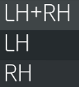 |
Available selections for the working cavity. |
 |
Single-cavity view. |
 |
Dual-cavity view with automatic selection. |
Further information
If the alarm occurs repeatedly or it is not resolved, contact the CEMAS Elettra assistance. The contact details can be found in MACHINE DIAGNOSTICS/ASSISTANCE.
M31003-0.XX - Automatic cycle - Part contact timeout
The time within which the parts must come into contact has been exceeded.
Parts contact quota configuration
The height set to reach the workpiece contact position is incorrect.
Change the workpiece contact parameter on the TOOL SETTINGS/POSITIONS page.
Further information
If the alarm occurs repeatedly or it is not resolved, contact the CEMAS Elettra assistance. The contact details can be found in MACHINE DIAGNOSTICS/ASSISTANCE.
M31004-0.XX - Automatic cycle - Cycle timeout
The maximum time set for completing the processing cycle in automatic mode has been exceeded.
The welding machine switches to manual mode automatically.
Further information
If the alarm occurs repeatedly or it is not resolved, contact the CEMAS Elettra assistance. The contact details can be found in MACHINE DIAGNOSTICS/ASSISTANCE.
M31005-0.XX - Automatic cycle - Fire safety procedure intervention
The maximum time that the mirror can be kept in the working position has been exceeded.
The machine opens and returns to the rest position automatically.
Further information
If the alarm occurs repeatedly or it is not resolved, contact the CEMAS Elettra assistance. The contact details can be found in MACHINE DIAGNOSTICS/ASSISTANCE.
M31006-0.XX - Automatic cycle - Confirm rejection request
At the end of the cycle, if scrap piece confirmation is enabled, the operator must confirm on the panel to allow the gate to open and/or the welded parts to be released.
Confirmation must be made on the CONTROL PAGE.
Tool loading cycle
...
M32000-0.XX - Tool load cycle - No connector selected
The type of connection plug for the tool has not been selected.
Select plug type
Select the type of plug installed on the tool on the TOOL SETUP/CONFIGURATION page.
Further information
If the alarm occurs repeatedly or it is not resolved, contact the CEMAS Elettra assistance. The contact details can be found in MACHINE DIAGNOSTICS/ASSISTANCE.
M32001-0.XX - Tool load cycle - Tool code not present
If the tool code is not readable or has not been defined, the current decoding field on the MACHINE DIAGNOSTICS/PLC/PIN DECODING page will show the value 0.
Check wiring
Check that the tool plug is correctly wired.
Further information
If the alarm occurs repeatedly or it is not resolved, contact the CEMAS Elettra assistance. The contact details can be found in MACHINE DIAGNOSTICS/ASSISTANCE.
M32002-0.XX - Tool load cycle - Rear tool change active
The tool change is active. To deactivate it, turn the selector switch located on the rear door back to its original position.
Tool unloading cycle
...
M33000-0.XX - Tool unloading cycle - Unload tool
The tool has not been unloaded from the welding machine.
Further information
If the alarm occurs repeatedly or it is not resolved, contact the CEMAS Elettra assistance. The contact details can be found in MACHINE DIAGNOSTICS/ASSISTANCE.
Archive management
...
M34000-0.XX - Archives management - Buffer full
Help not available
Further information
If the alarm occurs repeatedly or it is not resolved, contact the CEMAS Elettra assistance. The contact details can be found in MACHINE DIAGNOSTICS/ASSISTANCE.
M34001-0.XX - Archives management - Acquisition timeout
Help not available
Further information
If the alarm occurs repeatedly or it is not resolved, contact the CEMAS Elettra assistance. The contact details can be found in MACHINE DIAGNOSTICS/ASSISTANCE.
Tool columns
...
M35000-1.XX - Head - Tool columns - Columns not inserted
The columns have not been inserted into the designated slots on the tool to ensure correct stacking.
M35000-2.XX - Table - Tool columns - Columns not inserted
The columns have not been inserted into the designated slots on the tool to ensure correct stacking.
Check column insertion
Check that the columns are present and correctly inserted in the slots provided for column assembly.
Sensors not working
Check the functionality of the sensors, ensuring that:
- the electrical contact has been inserted;
- the sensor cable has not been damaged;
- the sensor is correctly calibrated;
- the sensor is properly tightened.
If necessary, replace the faulty sensor.
Further information
If the alarm occurs repeatedly or it is not resolved, contact the CEMAS Elettra assistance. The contact details can be found in MACHINE DIAGNOSTICS/ASSISTANCE.
M35000-3.XX - Mirror (rear/left) - Tool columns - Columns not inserted
The columns have not been inserted into the designated slots on the tool to ensure correct stacking.
M35001-3.XX - Mirror (rear/left) - Tool columns - Inserted columns
The columns are inserted into the seat provided on the tool for column formation.
M35001-2.XX - Table - Tool columns - Inserted columns
The columns are inserted into the seat provided on the tool for column formation.
Check column insertion
Check that the columns are there and, if necessary, remove them from the places provided for column forming and position them in the places provided for storage.
Sensors not working
Check the functionality of the sensors, ensuring that:
- the electrical contact has been inserted;
- the sensor cable has not been damaged;
- the sensor is correctly calibrated;
- the sensor is properly tightened.
If necessary, replace the faulty sensor.
Further information
If the alarm occurs repeatedly or it is not resolved, contact the CEMAS Elettra assistance. The contact details can be found in MACHINE DIAGNOSTICS/ASSISTANCE.
M35001-1.XX - Head - Tool columns - Inserted columns
The columns are inserted into the seat provided on the tool for column formation.
M35002-3.XX - Mirror (rear/left) - Tool columns - Columns in incorrect position
The tool columns are not all in the desired position.
M35002-2.XX - Table - Tool columns - Columns in incorrect position
The tool columns are not all in the desired position.
Check column position
Check that all columns are inserted in the desired position:
- if the tool must be stacked for transport, the columns must all be positioned in the slots provided for stacking;
- if the tool must be installed on the welding machine, the columns must all be positioned in the slots provided for storage.
Sensors not working
Check the functionality of the sensors, ensuring that:
- the electrical contact has been inserted;
- the sensor cable has not been damaged;
- the sensor is correctly calibrated;
- the sensor is properly tightened.
If necessary, replace the faulty sensor.
Further information
If the alarm occurs repeatedly or it is not resolved, contact the CEMAS Elettra assistance. The contact details can be found in MACHINE DIAGNOSTICS/ASSISTANCE.
M35002-1.XX - Head - Tool columns - Columns in incorrect position
The tool columns are not all in the desired position.
M35003-3.XX - Mirror (rear/left) - Tool columns - Non-resting columns
Columns not at rest
M35003-2.XX - Table - Tool columns - Non-resting columns
Columns not at rest
M35003-1.XX - Head - Tool columns - Non-resting columns
Rest not present
M35004-1.XX - Head - Tool columns - Columns at rest
Columns at rest
M35004-2.XX - Table - Tool columns - Resting columns
Columns at rest
M35004-3.XX - Mirror (rear/left) - Tool columns - Resting columns
Columns at rest
Laser source
...
IR
...
M39100-0.XX - IR Rack - Communication error
The IRM module does not communicate with the welding machine PLC.
IRM module connection
Check that the IRM module is properly connected.
Check both the power cable and the Ethernet cable.
Further information
If the alarm occurs repeatedly or it is not resolved, contact the CEMAS Elettra assistance. The contact details can be found in MACHINE DIAGNOSTICS/ASSISTANCE.
M39000-0.XX - IR - Maximum Temperature Card Reached
The IRM modules inside the electrical panel have reached their maximum temperature.
Check cooling system
Check that the air conditioner on the electrical panel is working and that the IRM modules are functioning correctly.
Replace IRM module
If the alarm cannot be resolved, the IRM module must be replaced.
Contact CEMAS Elettra for assistance.
Further information
If the alarm occurs repeatedly or it is not resolved, contact the CEMAS Elettra assistance. The contact details can be found in MACHINE DIAGNOSTICS/ASSISTANCE.
M39200-0.XX - IR Box - Breaker triggered
The automatic switch, known as the thermal switch, relating to the IRM module has tripped.
Automatic switch (thermal) tripped
If the automatic switch, known as the thermal switch, has tripped:
- check that the automatic switch indicator is not set too low;
- reset the switch and check that it does not trip again;
- check that the component is working properly.
In the event of a fault or malfunction, replace the component.
Further information
If the alarm occurs repeatedly or it is not resolved, contact the CEMAS Elettra assistance. The contact details can be found in MACHINE DIAGNOSTICS/ASSISTANCE.
M39201-0.XX - IR Box - Not ready
The IRM module box is not ready.
Please wait until the process is complete; if the problem persists, check that the rack is wired correctly.
Further information
If the alarm occurs repeatedly or it is not resolved, contact the CEMAS Elettra assistance. The contact details can be found in MACHINE DIAGNOSTICS/ASSISTANCE.
M39101-0.XX - IR Rack - Zone
IR zone alarm.
Alarm not displayed.
M39001-0.XX - IR - Output Voltage Too High
The voltage value output from the IRM module exceeded 35 V.
Check resistance
Go to the TOOL SETTINGS/INFRARED PARAMETERS page and check that the resistance value shown in the current values box is between 0.1 Ω and 2.2 Ω.
If the value is not within these limits, the IRM module cannot operate.
Further information
If the alarm occurs repeatedly or it is not resolved, contact the CEMAS Elettra assistance. The contact details can be found in MACHINE DIAGNOSTICS/ASSISTANCE.
M39002-0.XX - IR - Output Power Too High
The IRM device is either emitting too much voltage (therefore the output voltage is too high) or it is emitting too much current (therefore the IRM module has a fault).
Check resistance
Go to the TOOL SETTINGS/INFRARED PARAMETERS page and check that the resistance value shown in the current values box is between 0.1 Ω and 2.2 Ω.
If the value is not within these limits, the IRM module cannot operate.
Check power
Go to the TOOL SETTINGS/INFRARED PARAMETERS page and check that the power value in the current values box does not exceed 800 W.
If the power value exceeds this value, you must reduce the values of the standby power and full power 1 parameters.
Further information
If the alarm occurs repeatedly or it is not resolved, contact the CEMAS Elettra assistance. The contact details can be found in MACHINE DIAGNOSTICS/ASSISTANCE.
M39102-0.XX - IR Rack - Box 1
Box alarm 1 IR zones.
Alarm not displayed.
M39103-0.XX - IR Rack - Box 2
2-zone IR box alarm.
Alarm not displayed.
M39003-0.XX - IR - Input Voltage Too Low
The IRM module is not receiving enough power.
Replace IRM module
If the alarm cannot be resolved, the IRM module must be replaced.
Contact CEMAS Elettra for assistance.
Further information
If the alarm occurs repeatedly or it is not resolved, contact the CEMAS Elettra assistance. The contact details can be found in MACHINE DIAGNOSTICS/ASSISTANCE.
...
...
M39104-0.XX - IR Rack - Box 3
3-zone IR box alarm.
Alarm not displayed.
M39004-0.XX - IR - Temperature Too Low
The thermocouples mounted on the mirror detect a temperature lower than that required for welding.
Waiting for heating
Wait until the mirror reaches the desired temperature.
Change power
Go to the TOOL SETTINGS/INFRARED PARAMETERS page and change the value of the standby parameter in the power box.
Change temperature setpoint
Go to the TOOL SETTINGS/INFRARED PARAMETERS page and change the value of temperature setpoint in the temperature sensor box.
Further information
If the alarm occurs repeatedly or it is not resolved, contact the CEMAS Elettra assistance. The contact details can be found in MACHINE DIAGNOSTICS/ASSISTANCE.
M39005-0.XX - IR - Resistance not OK
The IRM module detects an anomaly in the mirror resistors.
Check IRM wiring
Check that the electrical connections between the IRM module and the mirror are working and intact.
Check resistance
Go to the TOOL SETTINGS/INFRARED PARAMETERS page and check that the resistance value shown in the current values box is between 0.1 Ω and 2.2 Ω.
If the value is not within these limits, the IRM module cannot operate.
...
...
Further information
If the alarm occurs repeatedly or it is not resolved, contact the CEMAS Elettra assistance. The contact details can be found in MACHINE DIAGNOSTICS/ASSISTANCE.
M39105-0.XX - IR Rack - Box 4
4-zone IR box alarm.
Alarm not displayed.
M39006-0.XX - IR - Output In Short Circuit
The resistance value read by the IRM is outside of the range.
...
...
Further information
If the alarm occurs repeatedly or it is not resolved, contact the CEMAS Elettra assistance. The contact details can be found in MACHINE DIAGNOSTICS/ASSISTANCE.
M39007-0.XX - IR - Resistance too high
The resistance value measured by the IRM module exceeds 2.2 Ω.
Check resistance
Go to the TOOL SETTINGS/INFRARED PARAMETERS page and check that the resistance value shown in the current values box is between 0.1 Ω and 2.2 Ω.
If the value is not within these limits, the IRM module cannot operate.
...
...
Replace heating element
Replace the heating element that does not fall within the limits.
Further information
If the alarm occurs repeatedly or it is not resolved, contact the CEMAS Elettra assistance. The contact details can be found in MACHINE DIAGNOSTICS/ASSISTANCE.
M39008-0.XX - IR - Resistance too low
The resistance value measured by the IRM module does not reach 0.1 Ω.
Check resistance
Go to the TOOL SETTINGS/INFRARED PARAMETERS page and check that the resistance value shown in the current values box is between 0.1 Ω and 2.2 Ω.
If the value is not within these limits, the IRM module cannot operate.
...
...
Replace heating element
Replace the heating element that does not fall within the limits.
Further information
If the alarm occurs repeatedly or it is not resolved, contact the CEMAS Elettra assistance. The contact details can be found in MACHINE DIAGNOSTICS/ASSISTANCE.
M39009-0.XX - IR - Temperature too high
The thermocouples mounted on the mirror detect a temperature higher than that required for welding.
Further information
If the alarm occurs repeatedly or it is not resolved, contact the CEMAS Elettra assistance. The contact details can be found in MACHINE DIAGNOSTICS/ASSISTANCE.
M39010-0.XX - IR - Not ready
The IRM module is starting up.
Please wait until the process is complete.
Further information
If the alarm occurs repeatedly or it is not resolved, contact the CEMAS Elettra assistance. The contact details can be found in MACHINE DIAGNOSTICS/ASSISTANCE.
M39011-0.XX - IR - Analogue temperature sensor
An anomaly has been detected on the mirror thermocouple.
Damaged thermocouple
Check that the thermocouple installed on the mirror is intact and working properly.
Check mirror plug wiring
Check that the mirror connection plug connections are intact and working.
Check IRM wiring
Check that the electrical connections between the IRM module and the mirror are working and intact.
Further information
If the alarm occurs repeatedly or it is not resolved, contact the CEMAS Elettra assistance. The contact details can be found in MACHINE DIAGNOSTICS/ASSISTANCE.
M39012-0.XX - IR - Connector not in parking position
The mirror connection plug is not in the parking position.
Plug in parking
Place the mirror connection plug in the appropriate slot located at the rear of the welding machine.
Further information
If the alarm occurs repeatedly or it is not resolved, contact the CEMAS Elettra assistance. The contact details can be found in MACHINE DIAGNOSTICS/ASSISTANCE.
M39013-0.XX - IR - Parking connector
The mirror connection plug is in the parking position.
Connect plug
Insert the mirror's connection plug into the socket located at the rear of the mirror.
Further information
If the alarm occurs repeatedly or it is not resolved, contact the CEMAS Elettra assistance. The contact details can be found in MACHINE DIAGNOSTICS/ASSISTANCE.
M39014-0.XX - IR - Communication with the PLC
Communication error with the PLC
M39015-0.XX - IR - Low current demand
The current required is below the minimum threshold.
M39016-0.XX - IR - Current required high
Requested current is above the maximum threshold
Laser Rack
...
Power Meter
...
Sistema Laser
...
Cooling system
...
Voltage monitoring
...
M44000-0.XX - Voltage control - Not present
The 24V power supply is not present even though the working conditions of the welding machine do not prevent it (switches and safety devices active).
Inspection of electrical panel
Quickly inspect the electrical panel to check that the switches for the various power supplies are intact and working.
Further information
If the alarm occurs repeatedly or it is not resolved, contact the CEMAS Elettra assistance. The contact details can be found in MACHINE DIAGNOSTICS/ASSISTANCE.
Protective Tools
...
M45000-3.XX - Mirror (rear/left) - Protective tools - Rest position timeout
The time limit for the movement of the mirror protection tools (rear/left) has been exceeded. The rest position has not been reached.
Pneumatic control
Check that all pneumatic tubes are properly connected and that there are no obstructions.
Check the continuity of the air flow, ensuring that: - no tubes are bent - no tubes are damaged - all tubes are properly connected
Sensors not working
Check the functionality of the sensors, ensuring that:
- the electrical contact has been inserted;
- the sensor cable has not been damaged;
- the sensor is correctly calibrated;
- the sensor is properly tightened.
If necessary, replace the faulty sensor.
Movement not completed
If the equipment guards do not complete the movement within the set time:
- check that the input set for the equipment guards is correct;
- check that the travel of the equipment guards is not obstructed by mechanical impediments.
Not enough time
The time set to move the tool guards is not enough to complete the movement.
Change the timeout time in MACHINE SETTINGS/GENERAL SETTINGS/TOOL INTERFACES.
Further information
If the alarm occurs repeatedly or it is not resolved, contact the CEMAS Elettra assistance. The contact details can be found in MACHINE DIAGNOSTICS/ASSISTANCE.
M45001-3.XX - Mirror (rear/left) - Protective tools - Work position timeout
The time allowed for moving the mirror (rear/left) protective tools has been exceeded. The working position has not been reached.
Pneumatic control
Check that all pneumatic tubes are properly connected and that there are no obstructions.
Check the continuity of the air flow, ensuring that: - no tubes are bent - no tubes are damaged - all tubes are properly connected
Sensors not working
Check the functionality of the sensors, ensuring that:
- the electrical contact has been inserted;
- the sensor cable has not been damaged;
- the sensor is correctly calibrated;
- the sensor is properly tightened.
If necessary, replace the faulty sensor.
...
...
Movement not completed
If the equipment guards do not complete the movement within the set time:
- check that the input set for the equipment guards is correct;
- check that the travel of the equipment guards is not obstructed by mechanical impediments.
Not enough time
The time set to move the tool guards is not enough to complete the movement.
Change the timeout time in MACHINE SETTINGS/GENERAL SETTINGS/TOOL INTERFACES.
Further information
If the alarm occurs repeatedly or it is not resolved, contact the CEMAS Elettra assistance. The contact details can be found in MACHINE DIAGNOSTICS/ASSISTANCE.
M45002-3.XX - Mirror (rear/left) - Protective tools - Rest position not released
The sensor that detects the rest position of the mirror protection tools (rear/left) continues to signal the position reached.
Pneumatic control
Check that all pneumatic tubes are properly connected and that there are no obstructions.
Check the continuity of the air flow, ensuring that: - no tubes are bent - no tubes are damaged - all tubes are properly connected
Tool guards locked
If the equipment guards do not move, check:
- for any mechanical obstructions preventing the equipment guards from moving; then remove the mechanical obstruction before moving the guards;
- that the equipment guards are working properly.
Sensors not working
Check the functionality of the sensors, ensuring that:
- the electrical contact has been inserted;
- the sensor cable has not been damaged;
- the sensor is correctly calibrated;
- the sensor is properly tightened.
If necessary, replace the faulty sensor.
Further information
If the alarm occurs repeatedly or it is not resolved, contact the CEMAS Elettra assistance. The contact details can be found in MACHINE DIAGNOSTICS/ASSISTANCE.
M45003-3.XX - Mirror (rear/left) - Protective tools - Working position not released
The sensor that detects the working position of the mirror tool guards (rear/left) continues to signal the position reached.
Pneumatic control
Check that all pneumatic tubes are properly connected and that there are no obstructions.
Check the continuity of the air flow, ensuring that: - no tubes are bent - no tubes are damaged - all tubes are properly connected
Tool guards locked
If the equipment guards do not move, check:
- for any mechanical obstructions preventing the equipment guards from moving; then remove the mechanical obstruction before moving the guards;
- that the equipment guards are working properly.
Sensors not working
Check the functionality of the sensors, ensuring that:
- the electrical contact has been inserted;
- the sensor cable has not been damaged;
- the sensor is correctly calibrated;
- the sensor is properly tightened.
If necessary, replace the faulty sensor.
Further information
If the alarm occurs repeatedly or it is not resolved, contact the CEMAS Elettra assistance. The contact details can be found in MACHINE DIAGNOSTICS/ASSISTANCE.
M45004-3.XX - Mirror (rear/left) - Protective tools - External alarm
External alarm for mirror protection tools (rear/left).
Alarm not displayed.
M45005-3.XX - Mirror (rear/left) - Protective tools - Both position feedback
Sensors that detect the working position and rest position of the mirror tools (rear/left) both signal the position reached.
Sensor positioning
Check that the sensors are correctly positioned: one sensor must check the working position and one sensor must check the rest position.
Reposition the sensors if necessary.
Sensors not working
Check the functionality of the sensors, ensuring that:
- the electrical contact has been inserted;
- the sensor cable has not been damaged;
- the sensor is correctly calibrated;
- the sensor is properly tightened.
If necessary, replace the faulty sensor.
Further information
If the alarm occurs repeatedly or it is not resolved, contact the CEMAS Elettra assistance. The contact details can be found in MACHINE DIAGNOSTICS/ASSISTANCE.
M45006-3.XX - Mirror (rear/left) - Protective tools - Both commands
The mirror protection tools (rear/left) have not been set correctly, as two different commands are active at the same time.
Reset controls
Check that the controls are set correctly. If necessary, change the controls in MACHINE SETTINGS/GENERAL SETTINGS/TOOL INTERFACES.
Further information
If the alarm occurs repeatedly or it is not resolved, contact the CEMAS Elettra assistance. The contact details can be found in MACHINE DIAGNOSTICS/ASSISTANCE.
Air interface
...
M46000-1.XX - Head - Air interface - Pressure switch
The pressure switch for discharging the valves relating to the head fixture is not working properly.
Pressure switch adjustment
Check that the pressure switch is set to a minimum pressure of 5 bar.
Electrically controlled coil
Check that the electric coil of the solenoid valve is working and controlled.
Valve functionality
Check that the valve switches regularly.
In case of malfunction, replace the component.
Further information
If the alarm occurs repeatedly or it is not resolved, contact the CEMAS Elettra assistance. The contact details can be found in MACHINE DIAGNOSTICS/ASSISTANCE.
M46000-2.XX - Panel - Air interface - Pressure switch
The pressure switch for discharging the valves relating to the table fixtures is not working properly.
Pressure switch adjustment
Check that the pressure switch is set to a minimum pressure of 5 bar.
Electrically controlled coil
Check that the electric coil of the solenoid valve is working and controlled.
Valve functionality
Check that the valve switches regularly.
In case of malfunction, replace the component.
Further information
If the alarm occurs repeatedly or it is not resolved, contact the CEMAS Elettra assistance. The contact details can be found in MACHINE DIAGNOSTICS/ASSISTANCE.
M46000-3.XX - Mirror (rear/left) - Air interface - Pressure switch
The pressure switch for the mirror valves (rear/left) is not working properly.
Pressure switch adjustment
Check that the pressure switch is set to a minimum pressure of 5 bar.
Electrically controlled coil
Check that the electric coil of the solenoid valve is working and controlled.
Valve functionality
Check that the valve switches regularly.
In case of malfunction, replace the component.
Further information
If the alarm occurs repeatedly or it is not resolved, contact the CEMAS Elettra assistance. The contact details can be found in MACHINE DIAGNOSTICS/ASSISTANCE.
M46001-3.XX - Mirror (rear/left) - Air interface - Safety inputs not present
At least one of the two sensors upstream of the pressure switch does not detect sufficient pressure.
M46001-1.XX - Head - Air interface - Safety inputs not present
At least one of the two sensors upstream of the pressure switch does not detect sufficient pressure.
M46001-2.XX - Table - Air interface - Safety inputs not present
At least one of the two sensors upstream of the pressure switch does not detect sufficient pressure.
Selection form
...
M47000-0.XX - Selective module - Error
The 24 V selective protection module is faulty.
Error check
Check the type of error using the LEDs on the module.
You can reset the module by pressing the LED that is flashing red.
Further information
If the alarm occurs repeatedly or it is not resolved, contact the CEMAS Elettra assistance. The contact details can be found in MACHINE DIAGNOSTICS/ASSISTANCE.
I/O interface
...
M48000-1.XX - Head - IO interface - Device not configured
The IO interface of the head is not configured.
Configure IO interface
If the IO interface has not been configured or has been configured incorrectly, contact CEMAS Elettra support to perform the configuration.
Further information
If the alarm occurs repeatedly or it is not resolved, contact the CEMAS Elettra assistance. The contact details can be found in MACHINE DIAGNOSTICS/ASSISTANCE.
M48000-2.XX - Board - IO interface - Device not configured
The board's IO interface is not configured.
Configure IO interface
If the IO interface has not been configured or has been configured incorrectly, contact CEMAS Elettra support to perform the configuration.
Further information
If the alarm occurs repeatedly or it is not resolved, contact the CEMAS Elettra assistance. The contact details can be found in MACHINE DIAGNOSTICS/ASSISTANCE.
M48001-1.XX - Head - IO interface - Device not accessible
The IO interface of the head is not accessible.
Connect IO interface
Check that the appropriate connection cable between the PLC and the IO interface is connected and check that communication is active by checking that the LEDs are lit.
Further information
If the alarm occurs repeatedly or it is not resolved, contact the CEMAS Elettra assistance. The contact details can be found in MACHINE DIAGNOSTICS/ASSISTANCE.
M48001-2.XX - Board - IO interface - Device not accessible
The board's IO interface is not accessible.
Connect IO interface
Check that the appropriate connection cable between the PLC and the IO interface is connected and check that communication is active by checking that the LEDs are lit.
Further information
If the alarm occurs repeatedly or it is not resolved, contact the CEMAS Elettra assistance. The contact details can be found in MACHINE DIAGNOSTICS/ASSISTANCE.
M48002-2.XX - Board - IO interface - Hardware error device
Hardware error reported by the board's IO interface.
Check hardware
Check that:
- the hardware is correctly installed;
- the hardware is intact.
In the event of a fault or malfunction, replace the component and contact CEMAS Elettra for assistance.
Further information
If the alarm occurs repeatedly or it is not resolved, contact the CEMAS Elettra assistance. The contact details can be found in MACHINE DIAGNOSTICS/ASSISTANCE.
M48002-1.XX - Head - IO interface - Hardware error device
Hardware error reported by the head IO interface.
Check hardware
Check that:
- the hardware is correctly installed;
- the hardware is intact.
In the event of a fault or malfunction, replace the component and contact CEMAS Elettra for assistance.
Further information
If the alarm occurs repeatedly or it is not resolved, contact the CEMAS Elettra assistance. The contact details can be found in MACHINE DIAGNOSTICS/ASSISTANCE.
Fibre measurement system
...
Sistema di copertura delle fibre
...
Machine valves
...
M51000-1.XX - Head - Machine valves - Device not configured
The valve unit for the welding machine head is not configured.
Configure valve units
The valve unit must be configured.
Contact CEMAS Elettra s.r.l. Service.
Further information
If the alarm occurs repeatedly or it is not resolved, contact the CEMAS Elettra assistance. The contact details can be found in MACHINE DIAGNOSTICS/ASSISTANCE.
M51000-3.XX - Mirror (rear/left) - Machine valves - Device not configured
The valve unit for the mirror (rear/left) of the welding machine is not configured.
Configure valve units
The valve unit must be configured.
Contact CEMAS Elettra s.r.l. Service.
Further information
If the alarm occurs repeatedly or it is not resolved, contact the CEMAS Elettra assistance. The contact details can be found in MACHINE DIAGNOSTICS/ASSISTANCE.
M51000-2.XX - Panel - Machine valves - Device not configured
The valve unit for the welding machine table is not configured.
Configure valve units
The valve unit must be configured.
Contact CEMAS Elettra s.r.l. Service.
Further information
If the alarm occurs repeatedly or it is not resolved, contact the CEMAS Elettra assistance. The contact details can be found in MACHINE DIAGNOSTICS/ASSISTANCE.
M51001-2.XX - Panel - Machine valves - Device not accessible
The valve unit for the welding machine table does not communicate with the PLC.
Valve unit ignition
Check that the valve unit is switched on and working, making sure that the LEDs are lit.
Check communication
Check that communication between the PLC and the valve unit is active by checking that the LED is lit.
Further information
If the alarm occurs repeatedly or it is not resolved, contact the CEMAS Elettra assistance. The contact details can be found in MACHINE DIAGNOSTICS/ASSISTANCE.
M51001-1.XX - Head - Machine valves - Device not accessible
The valve unit on the welding machine head does not communicate with the PLC.
Valve unit ignition
Check that the valve unit is switched on and working, making sure that the LEDs are lit.
Check communication
Check that communication between the PLC and the valve unit is active by checking that the LED is lit.
Further information
If the alarm occurs repeatedly or it is not resolved, contact the CEMAS Elettra assistance. The contact details can be found in MACHINE DIAGNOSTICS/ASSISTANCE.
M51001-3.XX - Mirror (rear/left) - Machine valves - Device not accessible
The valve unit for the mirror (rear/left) on the welding machine is not communicating with the PLC.
Valve unit ignition
Check that the valve unit is switched on and working, making sure that the LEDs are lit.
Check communication
Check that communication between the PLC and the valve unit is active by checking that the LED is lit.
Further information
If the alarm occurs repeatedly or it is not resolved, contact the CEMAS Elettra assistance. The contact details can be found in MACHINE DIAGNOSTICS/ASSISTANCE.
M51002-2.XX - Panel - Machine valves - Hardware error device
Hardware error detected on the valve unit related to the welding machine table.
Further information
If the alarm occurs repeatedly or it is not resolved, contact the CEMAS Elettra assistance. The contact details can be found in MACHINE DIAGNOSTICS/ASSISTANCE.
M51002-3.XX - Mirror (rear/left) - Machine valves - Hardware error device
Hardware error detected on the valve unit related to the mirror (rear/left) of the welding machine.
Further information
If the alarm occurs repeatedly or it is not resolved, contact the CEMAS Elettra assistance. The contact details can be found in MACHINE DIAGNOSTICS/ASSISTANCE.
M51002-1.XX - Head - Machine valves - Hardware error device
Hardware error detected on the valve unit related to the welding machine head.
Further information
If the alarm occurs repeatedly or it is not resolved, contact the CEMAS Elettra assistance. The contact details can be found in MACHINE DIAGNOSTICS/ASSISTANCE.
General machine
...
M52000-0.XX - General machine - Hardware safety
Problem detected on safety cards mounted on the PLC.
Further information
If the alarm occurs repeatedly or it is not resolved, contact the CEMAS Elettra assistance. The contact details can be found in MACHINE DIAGNOSTICS/ASSISTANCE.
M52001-0.XX - General machine - Checklist not completed
The welding machine checklist (CHECK-LIST) has not been completed.
Complete the checklist for the welding machine.
Further information
If the alarm occurs repeatedly or it is not resolved, contact the CEMAS Elettra assistance. The contact details can be found in MACHINE DIAGNOSTICS/ASSISTANCE.
M52002-0.XX - General machine - Required cycle test
Perform the machine cycle test.
After resetting the alarm, press the cycle start button with the welding machine in automatic mode. The welding machine will automatically start a machine cycle test, which will be performed at reduced speed and force or torque.
The machine cycle test is performed to check that all safety devices are working.
Further information
If the alarm occurs repeatedly or it is not resolved, contact the CEMAS Elettra assistance. The contact details can be found in MACHINE DIAGNOSTICS/ASSISTANCE.
M52003-0.XX - General machine - Initialisation confirmation required
Confirm the initialisation of the new programme entered on the PLC.
Further information
If the alarm occurs repeatedly or it is not resolved, contact the CEMAS Elettra assistance. The contact details can be found in MACHINE DIAGNOSTICS/ASSISTANCE.
M52004-0.XX - General machine - Movement constraints bypassed
Some movements of the welding machine are linked to others to prevent collisions or damage.
These restrictions can be bypassed using the bypass movement restrictions button on the MACHINE DIAGNOSTICS/MANUAL MOVEMENTS page.
Further information
If the alarm occurs repeatedly or it is not resolved, contact the CEMAS Elettra assistance. The contact details can be found in MACHINE DIAGNOSTICS/ASSISTANCE.
M52005-0.XX - General machine - External dimensions
External out-of-range signal not present. Check interconnections. Example: external robot must provide a signal MACHINE SETTINGS/GENERAL SETTINGS/COMPONENTS/SIGNALS PRESENT
M52006-0.XX - General machine - Programming error
PLC programming error. Contact CEMAS support
Planarity
...
M53000-2.XX - Planarity - Not performed
The procedure for checking the planarity of the table has not been performed or has not been completed.
Perform flatness tests
The flatness of the mobile plane must be checked.
The flatness check must be carried out by a CEMAS Elettra s.r.l. operator or under their direct supervision.
Further information
If the alarm occurs repeatedly or it is not resolved, contact the CEMAS Elettra assistance. The contact details can be found in MACHINE DIAGNOSTICS/ASSISTANCE.
M53001-2.XX - Planarity - Lower mirror not performed
The procedure for checking the planarity between the board and the mirror has not been performed or has not been completed.
M53002-2.XX - Planarity - Upper mirror not performed
The procedure for checking the planarity between the mirror and the head has not been performed or has not been completed.
ID Card Reader
...
M54000-0.XX - ID Key Reader - Device not configured
The ID key reader is not configured.
Configure ID key reader
The ID key reader must be configured.
Contact CEMAS Elettra s.r.l. Service.
Further information
If the alarm occurs repeatedly or it is not resolved, contact the CEMAS Elettra assistance. The contact details can be found in MACHINE DIAGNOSTICS/ASSISTANCE.
M54001-0.XX - ID Key Reader - Device not accessible
The ID key reader does not communicate with the PLC.
ID key reader ignition
Check that the ID key reader is switched on and working by checking that the LEDs are lit.
Check communication
Check that communication between the PLC and the ID key reader is active by checking that the LED is lit.
Further information
If the alarm occurs repeatedly or it is not resolved, contact the CEMAS Elettra assistance. The contact details can be found in MACHINE DIAGNOSTICS/ASSISTANCE.
M54002-0.XX - ID Key Reader - Hardware error device
Hardware error detected in the ID key reader.
Further information
If the alarm occurs repeatedly or it is not resolved, contact the CEMAS Elettra assistance. The contact details can be found in MACHINE DIAGNOSTICS/ASSISTANCE.
M54003-0.XX - ID Key Reader - ID Error
The code detected by the ID key reader is incorrect.
Use a key that is accepted by the reader.
Further information
If the alarm occurs repeatedly or it is not resolved, contact the CEMAS Elettra assistance. The contact details can be found in MACHINE DIAGNOSTICS/ASSISTANCE.
M54004-0.XX - ID Key Reader - Communication error
The ID key reader does not communicate with the welding machine's PLC.
Key ID reader connection
Check that the ID key reader is properly connected.
Check both the power cable and the Ethernet cable.
Further information
If the alarm occurs repeatedly or it is not resolved, contact the CEMAS Elettra assistance. The contact details can be found in MACHINE DIAGNOSTICS/ASSISTANCE.
M54005-0.XX - ID Key Reader - Disconnected
The ID key reader is not connected.
Check connection
Check that the serial cable connecting the PLC and the ID key reader is connected and intact.
Check communication
Check that communication between the PLC and the ID key reader is active by checking that the LED is lit.
Further information
If the alarm occurs repeatedly or it is not resolved, contact the CEMAS Elettra assistance. The contact details can be found in MACHINE DIAGNOSTICS/ASSISTANCE.
Camshaft assembly
...
M55000-3.XX - Mirror (rear/left) - Mirror arms - Master alarm
The master axis of the mirror (rear/left) cannot be moved.
Axis status coding
Check the current status of the axis on the MACHINE DIAGNOSTICS/MOTOR STATUS page.
Select the "INFO" icon of the blocked axis to view the current status of the axis, where the statuses, errors and active warnings are displayed.
Further information
If the alarm occurs repeatedly or it is not resolved, contact the CEMAS Elettra assistance. The contact details can be found in MACHINE DIAGNOSTICS/ASSISTANCE.
M55001-3.XX - Mirror (rear/left) - Mirror shafts - Slave alarm
The slave axis of the mirror (rear/left) cannot be moved.
Axis status coding
Check the current status of the axis on the MACHINE DIAGNOSTICS/MOTOR STATUS page.
Select the "INFO" icon of the blocked axis to view the current status of the axis, where the statuses, errors and active warnings are displayed.
Further information
If the alarm occurs repeatedly or it is not resolved, contact the CEMAS Elettra assistance. The contact details can be found in MACHINE DIAGNOSTICS/ASSISTANCE.
Virtual master axis
...
Mirror plate interface
...
M57000-3.XX - Mirror (rear/left) - Mirror plate interface - Not present
The presence sensor does not detect the plate interface on the mirror.
Assembling tools
Check that the tool is properly installed in the machine, making sure that it is centred.
Sensors not working
Check the functionality of the sensors, ensuring that:
- the electrical contact has been inserted;
- the sensor cable has not been damaged;
- the sensor is correctly calibrated;
- the sensor is properly tightened.
If necessary, replace the faulty sensor.
Further information
If the alarm occurs repeatedly or it is not resolved, contact the CEMAS Elettra assistance. The contact details can be found in MACHINE DIAGNOSTICS/ASSISTANCE.
M57001-3.XX - Mirror (rear/left) - Mirror plate interface - Incorrect position
The position sensor indicates that the plate interface on the mirror is not correctly positioned.
Assembling tools
Check that the tool is properly installed in the machine, making sure that it is centred.
Sensors not working
Check the functionality of the sensors, ensuring that:
- the electrical contact has been inserted;
- the sensor cable has not been damaged;
- the sensor is correctly calibrated;
- the sensor is properly tightened.
If necessary, replace the faulty sensor.
Further information
If the alarm occurs repeatedly or it is not resolved, contact the CEMAS Elettra assistance. The contact details can be found in MACHINE DIAGNOSTICS/ASSISTANCE.
M57002-3.XX - Mirror (rear/left) - Mirror plate interface - Present
The presence sensor detects the interface plate installed and correctly positioned on the mirror.
Remove tools
To perform the required operations, the tool already installed on the welding machine must be removed.
Start the tool unloading procedure from the TOOL CHANGE/TOOL CHANGE page.
Further information
If the alarm occurs repeatedly or it is not resolved, contact the CEMAS Elettra assistance. The contact details can be found in MACHINE DIAGNOSTICS/ASSISTANCE.
M57003-3.XX - Mirror (rear/left) - Mirror plate interface - CEMAS right position incorrect
The position sensor indicates that the right CEMAS adapter for the plate interface on the mirror is not correctly positioned.
Interface assembly
Check that the mirror plate interface adapter is facing in the correct direction according to the mirror connection plug on the welding machine.
Sensors not working
Check the functionality of the sensors, ensuring that:
- the electrical contact has been inserted;
- the sensor cable has not been damaged;
- the sensor is correctly calibrated;
- the sensor is properly tightened.
If necessary, replace the faulty sensor.
Further information
If the alarm occurs repeatedly or it is not resolved, contact the CEMAS Elettra assistance. The contact details can be found in MACHINE DIAGNOSTICS/ASSISTANCE.
M57004-3.XX - Mirror (rear/left) - Mirror plate interface - Left GVX not present
The presence sensor does not detect the left GVX adapter of the plate interface on the mirror.
Interface assembly
Check that the mirror plate interface adapter is facing in the correct direction according to the mirror connection plug on the welding machine.
Sensors not working
Check the functionality of the sensors, ensuring that:
- the electrical contact has been inserted;
- the sensor cable has not been damaged;
- the sensor is correctly calibrated;
- the sensor is properly tightened.
If necessary, replace the faulty sensor.
Further information
If the alarm occurs repeatedly or it is not resolved, contact the CEMAS Elettra assistance. The contact details can be found in MACHINE DIAGNOSTICS/ASSISTANCE.
M57005-3.XX - Mirror (rear/left) - Mirror plate interface - Left GVX position incorrect
The position sensor indicates that the left GVX adapter for the plate interface on the mirror is not correctly positioned.
Interface assembly
Check that the mirror plate interface adapter is facing in the correct direction according to the mirror connection plug on the welding machine.
Sensors not working
Check the functionality of the sensors, ensuring that:
- the electrical contact has been inserted;
- the sensor cable has not been damaged;
- the sensor is correctly calibrated;
- the sensor is properly tightened.
If necessary, replace the faulty sensor.
Further information
If the alarm occurs repeatedly or it is not resolved, contact the CEMAS Elettra assistance. The contact details can be found in MACHINE DIAGNOSTICS/ASSISTANCE.
M57006-3.XX - Mirror (rear/left) - Mirror plate interface - Right GVX not present
The presence sensor does not detect the right GVX adapter of the plate interface on the mirror.
Interface assembly
Check that the mirror plate interface adapter is facing in the correct direction according to the mirror connection plug on the welding machine.
Sensors not working
Check the functionality of the sensors, ensuring that:
- the electrical contact has been inserted;
- the sensor cable has not been damaged;
- the sensor is correctly calibrated;
- the sensor is properly tightened.
If necessary, replace the faulty sensor.
Further information
If the alarm occurs repeatedly or it is not resolved, contact the CEMAS Elettra assistance. The contact details can be found in MACHINE DIAGNOSTICS/ASSISTANCE.
M57007-3.XX - Mirror (rear/left) - Mirror plate interface - Right GVX position incorrect
The position sensor indicates that the right GVX adapter for the plate interface on the mirror is not correctly positioned.
Interface assembly
Check that the mirror plate interface adapter is facing in the correct direction according to the mirror connection plug on the welding machine.
Sensors not working
Check the functionality of the sensors, ensuring that:
- the electrical contact has been inserted;
- the sensor cable has not been damaged;
- the sensor is correctly calibrated;
- the sensor is properly tightened.
If necessary, replace the faulty sensor.
Further information
If the alarm occurs repeatedly or it is not resolved, contact the CEMAS Elettra assistance. The contact details can be found in MACHINE DIAGNOSTICS/ASSISTANCE.
Oops
...
M58000-0.XX - UPS - General alarm
The welding machine can be equipped with an uninterruptible power supply, known as UPS, to overcome temporary power failures.
The uninterruptible power supply is not working properly.
Alarm code
Display the alarm code on the monitor.
Report the code to CEMAS Elettra customer service for specific information on the alarm displayed.
Further information
If the alarm occurs repeatedly or it is not resolved, contact the CEMAS Elettra assistance. The contact details can be found in MACHINE DIAGNOSTICS/ASSISTANCE.
M58001-0.XX - UPS - Input voltage out of tolerance
The input voltage to the uninterruptible power supply is outside the permitted tolerances.
Further information
If the alarm occurs repeatedly or it is not resolved, contact the CEMAS Elettra assistance. The contact details can be found in MACHINE DIAGNOSTICS/ASSISTANCE.
M58002-0.XX - UPS - Battery faulty
The battery in the power supply unit is not working.
Change battery
Replace the battery in the uninterruptible power supply.
Refer to the specific manual for the commercial component.
Further information
If the alarm occurs repeatedly or it is not resolved, contact the CEMAS Elettra assistance. The contact details can be found in MACHINE DIAGNOSTICS/ASSISTANCE.
M58003-0.XX - UPS - Voltage failure
The uninterruptible power supply is not receiving power.
Check connection
Check that the uninterruptible power supply is properly connected.
Further information
If the alarm occurs repeatedly or it is not resolved, contact the CEMAS Elettra assistance. The contact details can be found in MACHINE DIAGNOSTICS/ASSISTANCE.
Tool trolley
...
M59000-0.XX - Tool trolley - Present
Trolley placed in the machine
M59001-0.XX - Tool trolley - Not available
Trolley not placed in the machine
M59002-0.XX - Tool trolley - Trolley not in the correct position
The positioning sensor indicates that the trolley is not correctly positioned.
Optional connectors
...
M60000-0.XX - Optional connectors - Not present
Optional connector not connected to tool.
M60001-0.XX - Optional connectors - Present
Optional connector connected to tool.
M60002-0.XX - Optional connectors - Incorrect position
Optional connectors connected to tool in an incomplete manner.
Electrical panel doors
...
M61000-0.XX - Electrical panel doors - Electrical panel door not closed
The door of the electrical panel is open. Check and close it to allow proper cooling and protection of the powered electrical components.
HP
...
Mirror rotation
...
M63206-3.XX - Mirror (rear/left) - Mirror rotation - Technological object alarm
The technological object that enables the movement of the mobile plane is in alarm mode.
A technological object is any component involved in the movement.
M63207-3.XX - Mirror (rear/left) - Mirror rotation - Positive overtravel alarm
The welding machine signals when the table has reached its maximum travel.
M63208-3.XX - Mirror (rear/left) - Mirror rotation - Negative overtravel alarm
The welding machine signals when the table has reached its negative overtravel.
Tool Conveyor
...
M64001-0.XX - Roller conveyor Tool - Timeout for carriage rest movement
The time limit for completing the movement to the rest position of the roller conveyor carriage that moves the tool on the table has been exceeded.
M64002-0.XX - Roller Conveyor Tool - Slide Movement Timeout
The time limit for completing the movement to the working position of the roller conveyor carriage that moves the tool onto the table has been exceeded.
M64003-0.XX - Roller Tool - Rest position of slide not released
The sensor that detects the rest position of the roller conveyor carriage continues to signal the position reached.
M64004-0.XX - Roller conveyor tool - Working position of slide not released
The sensor that detects the working position of the roller conveyor carriage continues to signal the position reached.
M64005-0.XX - Roller Conveyor Tool - External Slide Alarm
External alarm in the roller conveyor carriage on the table.
Alarm not displayed.
M64006-0.XX - Roller Conveyor Tool - Both slide position sensors
The sensors that detect the rest position and working position of the roller conveyor carriage both signal the position reached.
M64007-0.XX - Roller Tool - Both commands slide
The roller conveyor carriage controls have not been set correctly, as two different commands are active at the same time.
M64008-0.XX - Roller conveyor Tool - Timeout for movement, rest, clamping
The time limit for completing the movement to the rest position of the roller conveyor clamps that move the tool on the table has been exceeded.
M64009-0.XX - Roller Conveyor Tool - Work movement timeout clamping
The time limit for completing the movement to the working position of the roller conveyor clamps that move the tool onto the table has been exceeded.
M64010-0.XX - Roller Tool - Rest position clamping not released
The sensor that detects the rest position of the roller conveyor clamps continues to signal the position reached.
M64011-0.XX - Roller conveyor Tool - Working position clamping not released
The sensor that detects the working position of the roller conveyor clamps continues to signal the position reached.
M64012-0.XX - Roller Conveyor Tool - External clamping alarm
External alarm in the roller conveyor clamping on the table.
Alarm not displayed.
M64013-0.XX - Roller Conveyor Tool - Both position sensors clamping
The sensors that detect the rest position and working position of the roller conveyor clamping both signal the position reached.
M64014-0.XX - Roller Tool - Both clamping commands
The roller conveyor clamping controls have not been set correctly, as two different commands are active at the same time.
M64015-0.XX - Roller conveyor Tool - Rest movement timeout
The time limit for completing the movement to the rest position of the roller conveyor that moves the tool onto the table has been exceeded.
M64016-0.XX - Roller conveyor Tool - Work movement timeout
The time limit for completing the movement to the working position of the roller conveyor that moves the tool onto the table has been exceeded.
M64017-0.XX - Roller Tool - Rest position not released
The sensor that detects the rest position of the roller conveyor continues to signal the position reached.
M64018-0.XX - Roller conveyor Tool - Working position not released
The sensor that detects the working position of the roller conveyor continues to signal the position reached.
M64019-0.XX - Roller Conveyor Tool - Both position sensors
The sensors that detect the rest position and the working position of the roller conveyor both signal the position reached.
M64020-0.XX - Roller Tool - Equipment not present
The presence sensor does not detect the tool installed on the roller conveyor.
M64021-0.XX - Roller Tool - Tool present
The presence sensor detects the tool installed on the roller conveyor.