Tool Settings
The TOOL SETTINGS menu allows you to access the pages for displaying and configuring all the functions related to the tool installed on the machine, for setting the optimal welding cycle for the specific tool and for configuring the welding parameters.
Configuration
The CONFIGURATION page allows you to configure the general settings of the tool. These settings will be stored and used whenever the tool is inserted into the machine.
Configuration
In the configuration area, you can define:
- Tool height: enter the minimum tool height in mm;
- Aligned tool height: enter the total height of the correctly aligned tool in mm;
- Load on head: the possibility of loading the part to be welded on the welding machine head can be activated or deactivated using the button;
- Unload from head: the possibility of unloading the part from the welding machine head can be activated or deactivated using the button.
Alternative automatic cycle
…
Cycle time
In the cycle time area, you can define:
- Minimum: enter the minimum cycle time in s;
- Maximum: enter the maximum cycle time in s.
If the defined cycle times are not respected, an alarm will be triggered.
Piece picking
In the piece picking area it is possible to select how the parts to be welded are loaded onto the machine. The selectable options are:
- Disabled: the operator manually loads the parts to be welded onto the fixtures;
- Simple: the welding machine automatically performs the necessary operations to allow the upper part to be gripped on the upper fixture, without the operator having to do it;
- Undercut: the welding machine automatically performs the necessary operations to allow the upper part to be gripped on the upper fixture, without the operator having to perform it and considering the presence of an undercut to be overcome. There is an undercut when the shape of the part to be welded is such that it prevents its division and extraction from the cavity of the fixture without damaging the part itself;
- Undercut without movement in preheating: the welding machine automatically performs the necessary operations to allow the upper part to be gripped on the upper fixture, without the operator having to perform it and considering the presence of an undercut to be overcome on the fixtures. There is an undercut when the shape of the part to be welded is such that it prevents its division and extraction from the cavity of the fixture without damaging the part itself.
Plug type
In the plug type area, it is possible to select the plug type for connecting the tool to the welder. All tool signals such as presence and actuator signals pass through the plug. The possible options that can be selected are:
- None: possibility foreseen but does not allow the welder to start;
- Cemas 24: 24-pin manual plug;
- Cemas 32: 32-pin manual plug;
- GVX: automatic plug compatible with tool not manufactured by Cemas;
- Profinet: automatic plug;
- Smart tool: automatic plug.
Automatic plugs are present in all CAN OPEN tools. It is also possible to tick the pneumatic option, to define the presence of pneumatic connections in the plug.
CEMAS 24
24-pin plug that uses digital I/O.
CEMAS 32
32-pin plug using digital I/O.
GVX
Plug compatible with tools not manufactured by CEMAS Elettra s.r.l., which activates the CAN OPEN communication standard.
Pneumatic
You can tick the pneumatic option to define the presence of pneumatic connections in the plug, then define a pneumatic connection that can be associated with the connector used.
Smart tools
If I activate profinet, can I select the smart tool option when installing a smart tool in the machine?
Model selection
If the tool has two or more cavities, the model selection area appears on the CONFIGURATION page. In the model selection area it is possible to activate or deactivate the automatic selection of the model: the welding machine can automatically recognise if the processing cycle foresees the welding of parts in all the cavities present on the tool or only in the cavities present on a single side of the tool. If the automatic selection is disabled, it is necessary to manually define which side of the tool is to be used.
Front gate
…
Cavity configuration
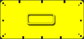
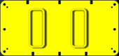
In the cavity configuration area, you can select the symbol representing the number and arrangement of cavities on the tool installed in the machine.
| ICON | ACTION |
|---|---|
 |
|
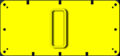 |
Tool consisting of a vertically positioned single cavity. |
 |
|
 |
|
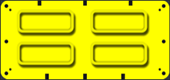 |
Tool consisting of four horizontally positioned cavities. |
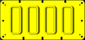 |
Tool consisting of four vertically positioned cavities. |
Actuators and Presences
The ACTUATORS AND PRESENCES page allows you to view and control the parameters of the objects on the tool, i.e. presences, actuators and vacuums. In ADVANCED CONFIGURATION, you can view and control the input and output commands of the tool.
Presences
The PRESENCE card allows you to view and control the parameters of the objects on the tool that control the parts to be welded. The objects performing the control can be:
- sensors;
- photocells;
- mechanical microswitches;
- fibre optics;
- more.
Presence list
The left-hand side of the PRESENCES card shows the list of configured presences. Presences can be configured as long as the add icon is present at the bottom of the list.
| ICON | ACTION |
|---|---|
 |
Add presence. |
 |
Delete presence. |
The status LED allows you to assess the condition of the presence: green indicates presence, off indicates absence, otherwise red indicates presence is in alarm.
Presence configuration
The right side of the PRESENCES card shows all the configurable fields of the individual presence selected.
Presence
Enter the identification name of the selected presence.
T02000-0.XX - Presence - Presence timeout
The time within which the presence of the object to be checked must be verified has been exceeded.
# Object not present or poorly positioned
The object to be checked is not present or has been positioned incorrectly.
If not present, position the object to be checked correctly.
If present, remove and replace the object, checking that the sensor LED changes status.
# Not enough time
The time set for performing the presence check is not sufficient to perform the operation that must be monitored by the sensor.
If necessary, change the presence timeout time in TOOL SETTINGS/ACTUATORS AND PRESENCES/PRESENCES.
# Check not performed
If the sensor that is supposed to check for presence is: - incorrectly positioned, check the position of the sensor and reposition it if necessary; - not calibrated, calibrate the sensor; - not working, check that it is actually working and replace it if necessary.
# Further information
If the alarm occurs repeatedly or it is not resolved, contact the CEMAS Elettra assistance. The contact details can be found in MACHINE DIAGNOSTICS/ASSISTANCE.
T02001-0.XX - Presence - Absence timeout
The time within which the absence of the object to be controlled must be verified has been exceeded.
# Object present or poorly positioned
The object that needs to be checked for absence is still present or has been positioned incorrectly.
If present, remove the object to be checked.
If not present, position and remove the object again, checking that the sensor LED changes status.
# Not enough time
The time set for performing the absence check is not sufficient to perform the operation that must be checked by the sensor.
If necessary, change the absence timeout time in TOOL SETTINGS/ACTUATORS AND PRESENCES/PRESENCES.
# Check not performed
If the sensor that should check for absence is: - incorrectly positioned, check the sensor position and reposition it if necessary; - not calibrated, calibrate the sensor; - not working, check that it is working properly and replace it if necessary.
# Further information
If the alarm occurs repeatedly or it is not resolved, contact the CEMAS Elettra assistance. The contact details can be found in MACHINE DIAGNOSTICS/ASSISTANCE.
T02002-0.XX - Presence - Incorrect connector pin address
The presence input configuration was not carried out properly.
# Reset inputs
Check that the inputs are set.
Check that the set inputs are correct.
If necessary, change the selection in TOOL SETTINGS/ACTUATORS AND PRESENCES/PRESENCES/INPUT.
# Further information
If the alarm occurs repeatedly or it is not resolved, contact the CEMAS Elettra assistance. The contact details can be found in MACHINE DIAGNOSTICS/ASSISTANCE.
T02003-0.XX - Presence - Not present
When activated, the sensor that must signal the presence, does not detect the presence of the object to be controlled.
# Sensors not working
Check the functionality of the sensors, ensuring that:
- the electrical contact has been inserted;
- the sensor cable has not been damaged;
- the sensor is correctly calibrated;
- the sensor is properly tightened.
If necessary, replace the faulty sensor.
# Object not present or poorly positioned
The object to be checked is not present or has been positioned incorrectly.
If not present, position the object to be checked correctly.
If present, remove and replace the object, checking that the sensor LED changes status.
# Reset inputs
Check that the inputs are set.
Check that the set inputs are correct.
If necessary, change the selection in TOOL SETTINGS/ACTUATORS AND PRESENCES/PRESENCES/INPUT.
# Further information
If the alarm occurs repeatedly or it is not resolved, contact the CEMAS Elettra assistance. The contact details can be found in MACHINE DIAGNOSTICS/ASSISTANCE.
T02004-0.XX - Presence - Not absent
When activated, the sensor that must signal the absence, detects the presence of the object to be controlled.
# Sensors not working
Check the functionality of the sensors, ensuring that:
- the electrical contact has been inserted;
- the sensor cable has not been damaged;
- the sensor is correctly calibrated;
- the sensor is properly tightened.
If necessary, replace the faulty sensor.
# Object present or poorly positioned
The object that needs to be checked for absence is still present or has been positioned incorrectly.
If present, remove the object to be checked.
If not present, position and remove the object again, checking that the sensor LED changes status.
# Reset inputs
Check that the inputs are set.
Check that the set inputs are correct.
If necessary, change the selection in TOOL SETTINGS/ACTUATORS AND PRESENCES/PRESENCES/INPUT.
# Further information
If the alarm occurs repeatedly or it is not resolved, contact the CEMAS Elettra assistance. The contact details can be found in MACHINE DIAGNOSTICS/ASSISTANCE.
T02005-0.XX - Presence - Incorrect command address
The presence command configuration was not carried out properly.
# Reset controls
Check that the presence controls are set correctly.
If necessary, change the controls by entering ADVANCED DISPLAY mode, in TOOL SETTINGS/ACTUATORS AND PRESENCES/PRESENCES/CONTROLS.
# Further information
If the alarm occurs repeatedly or it is not resolved, contact the CEMAS Elettra assistance. The contact details can be found in MACHINE DIAGNOSTICS/ASSISTANCE.
T02006-0.XX - Presence - Anti-repeat control
A welded piece is still present in the work area, thus activating the anti-repeat control.
# Remove welded piece
Remove the welded piece from the fixture to continue the production process.
# Sensors not working
Check the functionality of the sensors, ensuring that:
- the electrical contact has been inserted;
- the sensor cable has not been damaged;
- the sensor is correctly calibrated;
- the sensor is properly tightened.
If necessary, replace the faulty sensor.
# Further information
If the alarm occurs repeatedly or it is not resolved, contact the CEMAS Elettra assistance. The contact details can be found in MACHINE DIAGNOSTICS/ASSISTANCE.
Cavity - select the position
Select the tool interface on which wiring takes place.
Input
Select the gear key to access the input assignment card.
Presence time-out
Set the presence timeout, that is, the maximum time required for the selected presence to activate. If the timeout is exceeded, an alarm signal is generated.
Cavity - select cavity
Select the cavity of the active tool during the welding cycle.
Controls
Advanced view
Select the gear key to access the command assignment card. The key is visible only in ADVANCED CONFIGURATION mode.
Absence time-out
Set the absence timeout, that is, the maximum time required for the selected presence to deactivate. If the timeout is exceeded, an alarm signal is generated.
Delay ON
Advanced view
Set the delay time for switching on the presence, or the minimum presence detection time. The signal received by the presence is not stable when switched on. The definition of an ON time allows you to stabilise the signal received by the presence. After the minimum time entered, the signal operation will certainly be stable. The field is visible only in ADVANCED CONFIGURATION mode.
Delay OFF
Advanced view
Set the delay time for presence switch-off. The signal received by the presence is not stable when switched off. The definition of an OFF time allows you to stabilise the signal received by the presence. After the minimum time entered, the signal operation will certainly be stable. The field is visible only in ADVANCED CONFIGURATION mode.
Model selection
Enable or disable the presence for the automatic model selection. By activating the function, the presence will be used to detect the part to be welded in the cavity and thus allow the automatic selection of the model for the parameters of the welding cycle to be performed.
Anti-repetition
Select activation (YES) or deactivation (NO) of the anti-repetition. This function makes it possible to avoid starting a new welding cycle without unloading the piece welded in the previous welding cycle.
Contact
Advanced view
Select the functionality of the signal received by the presence: NO for normally open contact, NC for normally closed contact. The field is visible only in ADVANCED CONFIGURATION mode.
Actuators
The ACTUATORS card enables the display and control of the parameters of the objects on the tool that move the tool instrumentation. The objects performing the movements can be:
- clamps;
- slides;
- ejectors;
- actuators;
- more.
Actuators list
The left side of the ACTUATORS card shows the list of configured actuators. The listed actuator may consist of a single object or of a group of objects which are, however, managed as a single actuator. Actuators can be configured as long as the add icon is present at the bottom of the list.
| ICON | ACTION |
|---|---|
|
Add actuator. |
|
Delete actuator. |
The rest or work LED allows you to check what condition the actuator is in: if the rest LED is on, then the actuator is in the rest position; if the work LED is on, then the actuator is in the work position.
Actuators configuration
The right side of the ACTUATORS card shows all the configurable fields of the single actuator selected.
Actuator
Enter the identification name of the selected actuator. On the side are two buttons: work and rest. They allow a work and rest test of the selected actuator if the machine is set in non-automatic cycle. The LED associated with the button provides more specific information on the action of the selected test:
- green LED: work/rest achieved;
- yellow LED: work/rest in operation;
- red LED: work/rest in error; an alarm is triggered.
T01000-0.XX - Actuator - Rest position timeout
The time within which the movement must be completed has been exceeded; therefore, the actuator has not reached the rest position.
# Pneumatic control
Check that all pneumatic tubes are properly connected and that there are no obstructions.
Check the continuity of the air flow, ensuring that: - no tubes are bent - no tubes are damaged - all tubes are properly connected
# Movement not completed
If the actuator does not complete the movement within the set time:
- check that the input set for the actuator is correct;
- check that the actuator stroke is not obstructed by mechanical impediments.
# Sensors not working
Check the functionality of the sensors, ensuring that:
- the electrical contact has been inserted;
- the sensor cable has not been damaged;
- the sensor is correctly calibrated;
- the sensor is properly tightened.
If necessary, replace the faulty sensor.
# Not enough time
The time set to perform the actuator movement is not sufficient to complete it.
If necessary, change the timeout time in TOOL SETTINGS/ACTUATORS AND PRESENCES/ACTUATORS.
# Further information
If the alarm occurs repeatedly or it is not resolved, contact the CEMAS Elettra assistance. The contact details can be found in MACHINE DIAGNOSTICS/ASSISTANCE.
T01001-0.XX - Actuator - Work position timeout
The time within which the movement must be carried out has been exceeded; therefore, the actuator has not reached the work position.
# Sensors not working
Check the functionality of the sensors, ensuring that:
- the electrical contact has been inserted;
- the sensor cable has not been damaged;
- the sensor is correctly calibrated;
- the sensor is properly tightened.
If necessary, replace the faulty sensor.
# Movement not completed
If the actuator does not complete the movement within the set time:
- check that the input set for the actuator is correct;
- check that the actuator stroke is not obstructed by mechanical impediments.
# Pneumatic control
Check that all pneumatic tubes are properly connected and that there are no obstructions.
Check the continuity of the air flow, ensuring that: - no tubes are bent - no tubes are damaged - all tubes are properly connected
# Not enough time
The time set to perform the actuator movement is not sufficient to complete it.
If necessary, change the timeout time in TOOL SETTINGS/ACTUATORS AND PRESENCES/ACTUATORS.
# Further information
If the alarm occurs repeatedly or it is not resolved, contact the CEMAS Elettra assistance. The contact details can be found in MACHINE DIAGNOSTICS/ASSISTANCE.
T01002-0.XX - Actuator - Rest position not released
The sensor detecting the rest position of the actuator continues to signal the position reached.
# Pneumatic control
Check that all pneumatic tubes are properly connected and that there are no obstructions.
Check the continuity of the air flow, ensuring that: - no tubes are bent - no tubes are damaged - all tubes are properly connected
# Actuator locked
If the actuator does not move, check:
- whether there is a shutter preventing the actuator from moving; then, release the shutter before moving the actuator;
- check that the actuator stroke is not obstructed by mechanical impediments.
# Sensors not working
Check the functionality of the sensors, ensuring that:
- the electrical contact has been inserted;
- the sensor cable has not been damaged;
- the sensor is correctly calibrated;
- the sensor is properly tightened.
If necessary, replace the faulty sensor.
# Further information
If the alarm occurs repeatedly or it is not resolved, contact the CEMAS Elettra assistance. The contact details can be found in MACHINE DIAGNOSTICS/ASSISTANCE.
T01003-0.XX - Actuator - Work position not released
The sensor detecting the work position of the actuator continues to signal the position reached.
# Pneumatic control
Check that all pneumatic tubes are properly connected and that there are no obstructions.
Check the continuity of the air flow, ensuring that: - no tubes are bent - no tubes are damaged - all tubes are properly connected
# Actuator locked
If the actuator does not move, check:
- whether there is a shutter preventing the actuator from moving; then, release the shutter before moving the actuator;
- check that the actuator stroke is not obstructed by mechanical impediments.
# Sensors not working
Check the functionality of the sensors, ensuring that:
- the electrical contact has been inserted;
- the sensor cable has not been damaged;
- the sensor is correctly calibrated;
- the sensor is properly tightened.
If necessary, replace the faulty sensor.
# Further information
If the alarm occurs repeatedly or it is not resolved, contact the CEMAS Elettra assistance. The contact details can be found in MACHINE DIAGNOSTICS/ASSISTANCE.
T01004-0.XX - Actuator - External alarm
Error reported by the actuator concerning an external alarm.
Alarm not displayed.
T01005-0.XX - Actuator - Both position feedbacks
Both the sensors detecting the rest and work positions of the actuator signal the position reached.
# Sensor positioning
Check that the sensors are correctly positioned: one sensor must check the working position and one sensor must check the rest position.
Reposition the sensors if necessary.
# Sensors not working
Check the functionality of the sensors, ensuring that:
- the electrical contact has been inserted;
- the sensor cable has not been damaged;
- the sensor is correctly calibrated;
- the sensor is properly tightened.
If necessary, replace the faulty sensor.
# Further information
If the alarm occurs repeatedly or it is not resolved, contact the CEMAS Elettra assistance. The contact details can be found in MACHINE DIAGNOSTICS/ASSISTANCE.
T01006-0.XX - Actuator - Both commands
The actuator commands have not been set correctly, since two different commands are active at the same time.
# Reset controls
If the actuator displays this error, check that the commands are set correctly.
If necessary, change the commands in TOOL SETTINGS/ACTUATORS AND PRESENCES/ACTUATORS/COMMANDS, selecting the ADVANCED DISPLAY mode.
# Further information
If the alarm occurs repeatedly or it is not resolved, contact the CEMAS Elettra assistance. The contact details can be found in MACHINE DIAGNOSTICS/ASSISTANCE.
T01007-0.XX - Actuator - Not in rest position
The sensor detecting the rest position does not signal the presence of the actuator.
# Pneumatic control
Check that all pneumatic tubes are properly connected and that there are no obstructions.
Check the continuity of the air flow, ensuring that: - no tubes are bent - no tubes are damaged - all tubes are properly connected
# Actuator locked
If the actuator does not move, check:
- whether there is a shutter preventing the actuator from moving; then, release the shutter before moving the actuator;
- check that the actuator stroke is not obstructed by mechanical impediments.
# Sensors not working
Check the functionality of the sensors, ensuring that:
- the electrical contact has been inserted;
- the sensor cable has not been damaged;
- the sensor is correctly calibrated;
- the sensor is properly tightened.
If necessary, replace the faulty sensor.
# Further information
If the alarm occurs repeatedly or it is not resolved, contact the CEMAS Elettra assistance. The contact details can be found in MACHINE DIAGNOSTICS/ASSISTANCE.
T01008-0.XX - Actuator - Not in work position
The sensor detecting the work position does not signal the presence of the actuator.
# Pneumatic control
Check that all pneumatic tubes are properly connected and that there are no obstructions.
Check the continuity of the air flow, ensuring that: - no tubes are bent - no tubes are damaged - all tubes are properly connected
# Actuator locked
If the actuator does not move, check:
- whether there is a shutter preventing the actuator from moving; then, release the shutter before moving the actuator;
- check that the actuator stroke is not obstructed by mechanical impediments.
# Sensors not working
Check the functionality of the sensors, ensuring that:
- the electrical contact has been inserted;
- the sensor cable has not been damaged;
- the sensor is correctly calibrated;
- the sensor is properly tightened.
If necessary, replace the faulty sensor.
# Further information
If the alarm occurs repeatedly or it is not resolved, contact the CEMAS Elettra assistance. The contact details can be found in MACHINE DIAGNOSTICS/ASSISTANCE.
T01009-0.XX - Actuator - Incorrect command address
The actuator command configuration was not carried out properly.
# Reset controls
Check that the actuator controls are set correctly.
If necessary, change the controls by entering ADVANCED DISPLAY mode, in TOOL SETTINGS/ACTUATORS AND PRESENCES/ACTUATORS/CONTROLS.
# Further information
If the alarm occurs repeatedly or it is not resolved, contact the CEMAS Elettra assistance. The contact details can be found in MACHINE DIAGNOSTICS/ASSISTANCE.
T01010-0.XX - Actuator - Incorrect valve address
The actuator valve configuration was not carried out properly.
# Reset the valve
Check that a valve has been assigned to the actuator.
Check that the selected valve is correct.
If necessary, change the selection in TOOL SETTINGS/ACTUATORS AND PRESENCES/ACTUATORS.
# Further information
If the alarm occurs repeatedly or it is not resolved, contact the CEMAS Elettra assistance. The contact details can be found in MACHINE DIAGNOSTICS/ASSISTANCE.
T01011-0.XX - Actuator - Incorrect connector pin address
The actuator input configuration was not carried out properly.
# Reset inputs
Check that the inputs are set. Check that the set inputs are correct. If necessary, change the selection in TOOL SETTINGS/ACTUATORS AND PRESENCES/ACTUATORS/INPUTS.
# Further information
If the alarm occurs repeatedly or it is not resolved, contact the CEMAS Elettra assistance. The contact details can be found in MACHINE DIAGNOSTICS/ASSISTANCE.
Cavity - select the position
Select the tool interface on which wiring takes place.
Mode
Select the type of actuator selected. The actuator mode is automatically selected, namely, the generic mode that allows freer management of the object in the cyclogram. If I select one of the more specific actuator types present, it is no longer possible to manage the actuator in the cyclogram because it is automatically managed based on its function.
Good marking
The Good marking mode manages the actuator so that it creates a special mark on the correctly welded pieces.
Scrap marking
The Scrap marking mode manages the actuator so that it creates a special mark on the produced scrap pieces.
Piece picking slide
The Piece picking slide mode manages the actuator so that it performs the piece pick-up function.
Piece clamping
The Piece clamping mode manages the actuator so that it performs the clamping function during piece pick-up.
Select the valve
From the drop-down menu that appears, select the valve present on the machine relating to the chosen tool interface.
Input
Select the gear key to access the input assignment card.
Cavity - select cavity
Select the cavity of the active tool during the welding cycle.
Controls
Advanced view
Select the gear key to access the command assignment card. The key is visible only in ADVANCED CONFIGURATION mode.
Safety constraints
Select the gear key to access the safety constraints assignment card, or the priority in movements of the actuators to avoid impacts.
Rest time-out
Set the rest timeout, namely the time within which the movement must be completed, otherwise an alarm is triggered. The alarm is triggered both if the actuator does not complete the movement and if the actuator sensors do not work properly.
Work time-out
Set the work timeout, namely the time within which the movement must be performed, otherwise an alarm is triggered. The alarm is triggered both if the actuator does not complete the movement and if the actuator sensors do not work properly.
Rest delay
Advanced view
Set the time required to ensure the stability of the signal received from the rest sensor of the selected actuator, both for switching on or off. If the actuator does not have a sensor, the set time will be used to delay reaching the actuator rest position.
Work delay
Advanced view
Set the time required to ensure the stability of the signal received from the work sensor of the selected actuator, both for switching on or off. If the actuator does not have a sensor, the set time will be used to delay reaching the actuator work position.
Tool change position
…
Vacuums
The VACUUMS card enables the display and control of the parameters of the objects on the tool that hold the piece to be welded by means of vacuum. The holding objects can be:
- suction cups;
- vacuum cavities;
- more.
Vacuums list
The left-hand side of the VACUUM card shows the list of configured vacuums. Vacuums can be configured as long as the add icon is present at the bottom of the list.
| ICON | ACTION |
|---|---|
|
Add vacuum. |
|
Delete vacuum. |
The blow or vacuum LED allows you to check what condition the vacuum is in: if the blow LED is on, then the vacuum is generating a pressure to allow the part to detach; if the vacuum LED is on, then the vacuum is generating a negative pressure.
Vacuum configuration
The right side of the VACUUMS card shows all the configurable fields of the single vacuum selected.
Vacuum
Enter the identification name of the selected vacuum. On the side are two buttons: blow and vacuum. They allow a selected blow and vacuum test to be performed if the machine is set in non-automatic cycle. The LED associated with the button provides more specific information on the action of the selected test:
- green LED: blow/vacuum reached;
- yellow LED: blow/vacuum in operation;
- red LED: blow/vacuum in error; an alarm is triggered.
T03000-0.XX - Vacuum - Vacuum timeout
The time within which the achieved vacuum must be checked has been exceeded.
# Vacuum not reached
When the set vacuum is not reached, check whether: - the vacuum switch is not calibrated correctly; if so, check that the vacuum switch is working properly and calibrate it to - 0.65 bar; - the workpiece contact is not correct; if so, reposition the workpiece.
# Retention check
Check that the suction cup or vacuum path is working properly and effectively.
# Check not performed
The vacuum switch for vacuum control is not working or is not positioned correctly. Check that the vacuum switch is positioned correctly and that it is working properly. If necessary, reposition or replace the vacuum switch.
# Insufficient time
The time set for verifying the vacuum is not enough to carry out the operation that must be controlled by the sensor. If necessary, change the vacuum timeout time in TOOL SETTINGS/ACTUATORS AND PRESENCES/VACUUMS.
# Pneumatic control
Check that all pneumatic tubes are properly connected and that there are no obstructions.
Check the continuity of the air flow, ensuring that: - no tubes are bent - no tubes are damaged - all tubes are properly connected
# Further information
If the alarm occurs repeatedly or it is not resolved, contact the CEMAS Elettra assistance. The contact details can be found in MACHINE DIAGNOSTICS/ASSISTANCE.
T03001-0.XX - Vacuum - Invalid pump
If the vacuum is generated by a pump, this must be correctly associated to the specific vacuum.
# Incorrect configuration
The pump associated with the vacuum has not been configured correctly or the vacuum refers to a pump that has not been configured.
If necessary, change the pump configuration in MACHINE SETTINGS/GENERAL SETTINGS/COMPONENTS/TOOLS/VACUUM.
# Further information
If the alarm occurs repeatedly or it is not resolved, contact the CEMAS Elettra assistance. The contact details can be found in MACHINE DIAGNOSTICS/ASSISTANCE.
T03002-0.XX - Vacuum - Vacuum not released
The sensor detecting the vacuum continues to signal the achieved vacuum.
# Pneumatic control
Check that all pneumatic tubes are properly connected and that there are no obstructions.
Check the continuity of the air flow, ensuring that: - no tubes are bent - no tubes are damaged - all tubes are properly connected
# Retention check
Check that the suction cup or vacuum path is working properly and effectively.
# Sensors not working
Check the functionality of the sensors, ensuring that:
- the electrical contact has been inserted;
- the sensor cable has not been damaged;
- the sensor is correctly calibrated;
- the sensor is properly tightened.
If necessary, replace the faulty sensor.
# Piece not released
The piece subject to vacuum has not been released. Check that the vacuum is actually deactivated.
# Further information
If the alarm occurs repeatedly or it is not resolved, contact the CEMAS Elettra assistance. The contact details can be found in MACHINE DIAGNOSTICS/ASSISTANCE.
T03003-0.XX - Vacuum - Incorrect command address
The vacuum command configuration was not carried out properly.
# Reset controls
Check that the vacuum controls are set correctly. If necessary, change the controls by entering ADVANCED DISPLAY mode, in TOOL SETTINGS/ACTUATORS AND PRESENCES/VACUUM/CONTROLS.
# Further information
If the alarm occurs repeatedly or it is not resolved, contact the CEMAS Elettra assistance. The contact details can be found in MACHINE DIAGNOSTICS/ASSISTANCE.
T03004-0.XX - Vacuum - Inlet vacuum not configured
The vacuum input configuration was not carried out.
# Set inputs
Set the inputs correctly in MACHINE SETTINGS/GENERAL SETTINGS/COMPONENTS/TOOLS/INPUTS.
# Further information
If the alarm occurs repeatedly or it is not resolved, contact the CEMAS Elettra assistance. The contact details can be found in MACHINE DIAGNOSTICS/ASSISTANCE.
T03005-0.XX - Vacuum - Vacuum Lost
Help not available
# Pneumatic control
Check that all pneumatic tubes are properly connected and that there are no obstructions.
Check the continuity of the air flow, ensuring that: - no tubes are bent - no tubes are damaged - all tubes are properly connected
# Retention check
Check that the suction cup or vacuum path is working properly and effectively.
# Sensors not working
Check the functionality of the sensors, ensuring that:
- the electrical contact has been inserted;
- the sensor cable has not been damaged;
- the sensor is correctly calibrated;
- the sensor is properly tightened.
If necessary, replace the faulty sensor.
# Poorly positioned object
The object to be held by the vacuum is not present or has been positioned incorrectly. Insert the object correctly into the designated space.
# Further information
If the alarm occurs repeatedly or it is not resolved, contact the CEMAS Elettra assistance. The contact details can be found in MACHINE DIAGNOSTICS/ASSISTANCE.
Cavity - select the position
Select the tool interface on which wiring takes place.
Blow time-out
Set the blow timeout time, or the maximum time useful for the piece to be welded to be detached from the cavity. If the time is exceeded, an alarm is triggered.
Blow time
Set the blow time, namely a blow, equal to the time set here, that the welding machine performs after each detachment of the piece to be welded.
Vacuum time-out
Set the vacuum timeout time, namely the maximum time useful for the vacuum to be achieved. If the time is exceeded, an alarm is triggered.
Cavity - select cavity
Select the cavity of the active tool during the welding cycle.
Controls
Advanced view
Select the gear key to access the command assignment card. The key is visible only in ADVANCED CONFIGURATION mode.
Bundles
The BUNDLES card allows you to view and control the bundles present on the tool.
Bundles
The BUNDLES card shows a graphic representation of the bundles available on the welding machine and on the tool. A legend is available to facilitate reading.
| ICON | ACTION |
|---|---|
 |
Bundle not available on the welding machine. |
 |
Bundle present on the welding machine but not on the installed tool. |
 |
Bundle present on both the welding machine and the installed tool. |
 |
Bundle selected for configuration. |
Select bundle
Using the arrow keys next to the bundle number, you can select the bundle to be configured.
Enable bundle
The switch allows you to enable or disable the specific bundle.
Cavity - select cavity
Select the cavity of the active tool during the welding cycle.
Definition of ferrules
…
Input commands
Advanced view
The INPUT CONTROLS card, visible only in ADVANCED CONFIGURATION mode, allows you to view and control the parameters ..
Commands list
The left-hand side of the COMMANDS card shows the list of configured commands. You can configure commands as long as the add icon is present at the bottom of the list.
| ICON | ACTION |
|---|---|
|
Add command. |
|
Delete command. |
Input command configuration
The right side of the INPUT COMMANDS card shows all the configurable fields of the single command selected.
Input tool command
Enter the identification name of the selected command.
Cavity - select the position
Select the tool interface on which wiring takes place.
Signal
…
Input
Select the gear key to access the input assignment card.
Cavity - select cavity
Select the cavity of the active tool during the welding cycle.
Output commands
Advanced view
The OUTPUT CONTROLS card, visible only in ADVANCED CONFIGURATION mode, allows you to view and control the parameters ..
Commands list
The left-hand side of the COMMANDS card shows the list of configured commands. You can configure commands as long as the add icon is present at the bottom of the list.
| ICON | ACTION |
|---|---|
|
Add command. |
|
Delete command. |
Output command configuration
The right side of the OUTPUT COMMANDS card shows all the configurable fields of the single command selected.
Output tool command
Enter the identification name of the selected command.
Cavity - select the position
Select the tool interface on which wiring takes place.
Signal
…
Cavity - select cavity
Select the cavity of the active tool during the welding cycle.
Undercut
Advanced view
The UNDERCUT card, visible only in ADVANCED CONFIGURATION mode, if the undercut function is activated in the TOOL SETTINGS/CONFIGURATION, allows you to manage the elements for overcoming the undercut when loading the piece to be welded in the machine. An undercut occurs when the shape of the part to be welded is such that it cannot be split and extracted from the fixture cavity without damaging the part itself, i.e. when the part has angles of less than 90°, which effectively make the part indivisible from the fixture cavity. You can select:
- rest, if the undercut system is to be at rest during the loading of the workpiece;
- work, if the undercut system is to be at work during the workpiece loading phase.
Positions
The POSITIONS page allows you to view and configure the parameters necessary to perform the automatic movements of the welding machine. The welding machine must be set in manual mode in order to configure the parameters.
Table
The TABLE card is used to display and configure parameters relating to automatic movements linked to the welding machine table. When setting up the welding machine's processing cycle, it is possible to configure the dimensions of the automatic movements by manually moving the table using the arrow keys. Once the desired position has been reached, it is possible to validate the position using the acquire position key, located next to each specific position, or by manually writing the position readable above the arrow keys in the editable box.
Acquire position
| ICON | ACTION |
|---|---|
|
The acquire position key makes it possible to validate the position reached using the arrow keys, as the position to be reached during the automatic movements. |
Upper limit
The position that the table will reach as the maximum limit in the event that the parts to be welded are not present within the fixture area.
Piece contact
Position that the table will reach as the maximum limit to make contact with the piece to be welded.
Piece picking
Position that the table will reach to allow the upper piece on the upper fixture to be picked up without the operator performing it.
Out of clearance
Position that the table will reach to allow the necessary movements to avoid clutter during welding.
Piece detachment
Position that the table will reach as the maximum limit to perform the parts removal before the rapid descent.
Load
Position that the table will reach to allow the piece to be loaded/unloaded.
Table speed
Lifting table movement speed, expressed as a %, during the movements configurable in the card.
Slowdown
Position that the table will reach to begin the slowdown phase after the fast ascent phase and before starting the search for contact between the pieces.
Constraints
Select the gear key to access the constraints assignment pop-up, namely the priority in movements to avoid impacts.
Animation
The animation displays the positions defined schematically.
Movement
| Icon | ACTION |
|---|---|
 |
The ARROW keys allow you to move the table up or down. The movement is performed by holding the key down. The destination elevation is shown above the arrow keys. |
Cycle settings
The CYCLE SETTINGS page allows to view and program the various movements that the machine will have to carry out during the welding cycle steps. Programmable drives are actuators, presences and vacuums.
Welding parameters
The WELDING PARAMETERS page allows the welder parameters to be set for the various phases that make up the workpiece processing cycle. The workpiece processing cycle is divided into stages to improve the quality of the weld and to avoid workpiece breakage. Each processing cycle must consist of at least two steps: stabilisation step, welding cycle steps and cooling step. To improve welding quality, the welding cycle can be split up to a maximum of 10 steps, i.e. as long as the add icon is present.
| ICON | ACTION |
|---|---|
|
Add phase. |
|
Delete phase. |
If the assembled tool is divided into left and right sides, there may be several cards that allow parameters to be set for each side (LH card for the left side, RH card for the right side) and for both sides simultaneously (LH+RH card).
Stabilisation step
The STABILISATION STEP is the processing cycle step that allows you to stabilise reading of the transducer signal. The time set for executing the stabilisation step begins to be counted when the transducer’s signal is stable.
Time
Set the step execution time, expressed in s, by writing the value in the editable field.
Time/Depth
If the phase in question does not allow the welding mode to be selected or the selected welding mode is time, then set the phase execution time, expressed in s, by writing the value in the editable field. If the welding mode selected for the phase in question is relative depth or absolute depth, then set the welding depth to be reached during the phase, expressed in mm, by writing the value in the editable field.
Force
Set the force exerted by the table during the step, expressed in kgf, by writing the value in the editable field.
Adjustment step
OptionAdvanced view
The ADJUSTMENT STEP is the processing cycle step that follows the stabilisation step and makes it possible to adjust the pieces inside the fixture, once they touch each other, generating a short vibration. The adjustment is optional as it is not always necessary to adjust the pieces in the fixture. Act on the switch to activate the adjustment step. If the adjustment is carried out, the transducers are reset at the end of this step; therefore, reading of the transducer signals is no longer stabilised.
Time
Set the step execution time, expressed in s, by writing the value in the editable field.
Time/Depth
If the phase in question does not allow the welding mode to be selected or the selected welding mode is time, then set the phase execution time, expressed in s, by writing the value in the editable field. If the welding mode selected for the phase in question is relative depth or absolute depth, then set the welding depth to be reached during the phase, expressed in mm, by writing the value in the editable field.
Force
Set the force exerted by the table during the step, expressed in kgf, by writing the value in the editable field.
Welding step
The WELDING STEP is a portion of the processing cycle in which welding is actually carried out. It is useful to divide a welding cycle into several steps to improve monitoring of the welding and thus obtain a higher quality of the welding joint. Each welding step can be monitored in different ways, by selecting the type of control to be carried out.
Type
Select the welding mode for the step considered between time, relative depth and absolute depth, using the drop-down menu. If the selected mode is time, it will be possible to set only the step execution time. If the selected mode is relative depth or absolute depth, it will be possible to set only the force exerted by the table during the step.
Time
Set the step execution time, expressed in s, by writing the value in the editable field.
Time/Depth
If the phase in question does not allow the welding mode to be selected or the selected welding mode is time, then set the phase execution time, expressed in s, by writing the value in the editable field. If the welding mode selected for the phase in question is relative depth or absolute depth, then set the welding depth to be reached during the phase, expressed in mm, by writing the value in the editable field.
Force
Set the force exerted by the table during the step, expressed in kgf, by writing the value in the editable field.
Depth
Set the welding depth to be reached during the step, expressed in mm, by writing the value in the editable field.
Laser source
Set the emission powers of the laser source bundles enabled during the phase.
Bundles
The BUNDLES card shows a graphic representation of the bundles available on the welding machine and on the tool. A legend is available to facilitate reading.
| ICON | ACTION |
|---|---|
|
Bundle not available on the welding machine. |
|
Bundle present on the welding machine but not on the installed tool. |
|
Bundle present on both the welding machine and the installed tool. |
|
Bundle selected for configuration. |
Select bundle
Using the arrow keys next to the bundle number, you can select the bundle to be configured.
Power
Using the slider, you can set the transmission power of the selected bundle.
Cooling step
The COOLING STEP is the processing cycle step that follows all the welding cycle steps and allows the welding joint to cool down before the welded piece is unloaded from the welding machine. This avoids potential damage to the weld just performed.
Time
Set the step execution time, expressed in s, by writing the value in the editable field.
Time/Depth
If the phase in question does not allow the welding mode to be selected or the selected welding mode is time, then set the phase execution time, expressed in s, by writing the value in the editable field. If the welding mode selected for the phase in question is relative depth or absolute depth, then set the welding depth to be reached during the phase, expressed in mm, by writing the value in the editable field.
Force
Set the force exerted by the table during the step, expressed in kgf, by writing the value in the editable field.
Welding limits
The WELDING LIMITS are parameters that must be set during the first processing cycle of the part to be welded and refined in subsequent cycles, to define acceptable execution ranges of the piece processing cycle, i.e. in which a good welded piece is generated. If the defined ranges are exceeded during the processing cycle, the welded piece is considered as scrap. The most suitable range will be defined depending on the parts to be welded.
Welding time
Execution time of the entire welding cycle, i.e. time in which the vibration is actually generated, expressed in s. If the real welding time is not within the set limits, the automatic processing cycle of the welding machine will not be interrupted, but the machine will indicate a fault by means of an alarm and will generate a scrap piece.
Upper limit
Set the upper limit, writing the value in the editable field.
Lower limit
Set the lower limit, writing the value in the editable field.
Real
Display of the real value read by the welding machine. If the real value is not within the lower and upper limits, the welding machine will indicate a fault by means of an alarm and will generate a scrap piece.
Welding depth
Welding depth to be reached during the entire welding cycle, expressed in mm. If the real welding depth is not within the set limits, the automatic processing cycle of the welding machine will not be interrupted, but the machine will indicate a fault by means of an alarm and will generate a scrap piece.
Upper limit
Set the upper limit, writing the value in the editable field.
Lower limit
Set the lower limit, writing the value in the editable field.
Real
Display of the real value read by the welding machine. If the real value is not within the lower and upper limits, the welding machine will indicate a fault by means of an alarm and will generate a scrap piece.
Welding start position
Height at which the vibration actually begins to be generated for welding, expressed in mm. If a tool is installed on the welding machine that has not yet been saved, the welding start position must be set as follows:
- LOWER LIMIT = 0.00 mm;
- UPPER LIMIT = 800.00 mm.
At the end of the first welding cycle, it will be necessary to refine the welding limits by referring to the actual values reported. Once the limits have been defined, if the welding start position is not within the set limits, the automatic processing cycle of the welding machine will be interrupted and the table returned to its basic position. The welding machine will indicate a fault by means of an alarm and will generate a scrap piece.
Upper limit
Set the upper limit, writing the value in the editable field.
Lower limit
Set the lower limit, writing the value in the editable field.
Real
Display of the real value read by the welding machine. If the real value is not within the lower and upper limits, the welding machine will indicate a fault by means of an alarm and will generate a scrap piece.
Welding end position
Position at which the generation of vibration ends, thus ending the creation of the weld joint, expressed in mm. If the actual end-of-weld position is not within the set limits, the automatic welding machine cycle will not be interrupted, but the machine will signal an anomaly via an alarm and generate a reject piece.
Upper limit
Set the upper limit, writing the value in the editable field.
Lower limit
Set the lower limit, writing the value in the editable field.
Real
Display of the real value read by the welding machine. If the real value is not within the lower and upper limits, the welding machine will indicate a fault by means of an alarm and will generate a scrap piece.