Machine State
The MACHINE STATUS menu allows you to access the pages that provide information on what is happening to the machine in that precise moment, i.e. steps and status of the welding cycle in progress or just completed, machine production history, any alarms triggered and alarm history.
Control page
The CONTROL PAGE allows the welding cycle to be monitored in all its phases and characteristics. The CONTROL PAGE is normally displayed by the operator during the welding cycle of the machine.
Welding time
The WELDING TIME, expressed in seconds [s], is the duration during which the actual welding of the parts to be joined takes place.
Welding depth
The WELDING DEPTH, expressed in millimetres [mm], is the penetration of the molten material, i.e. the measured displacement of the table from the start of the plastic melting process to the end of the welding phase. It is determined by the force exerted by the table on the components to be joined and by the intensity of the welding process. For vibration machines, the depth increases as the vibration amplitude increases.
Cycle time
The CYCLE TIME, expressed in s, is the time taken by the machine to perform a whole welding cycle.
Vibration frequency
The VIBRATION FREQUENCY, expressed in Hz, is the number of oscillations produced by the welding tools per unit of time. The vibration frequency is specific to each application. It also depends on the size and weight of the fixture. As the weight and/or size increases, the vibration frequency decreases.
Welding result
The WELDING RESULT indicates whether the weld performed during the recently completed processing cycle was successful (green light illuminated) or resulted in a reject (red light illuminated). The welding result is determined by the welding parameters set in TOOL SETTINGS/WELDING PARAMETERS and by the welding limits set in TOOL SETTINGS/WELDING PARAMETERS/WELDING LIMITS.
Welding parameters
The WELDING PARAMETERS button allows direct access to the WELDING PARAMETERS page. The button is only visible to authorised users.
Chart
The GRAPH allows you to monitor the entire welding cycle as it runs. It displays the main results of the welding cycle, namely the table force (expressed in kgf), the welding depth (expressed in mm) and the vibration amplitude (expressed in mm). All results are displayed as a function of cycle time (expressed in s).
The graph area immediately shows the various phases of the welding cycle, automatically dividing the graph at each completed phase.
Within the graph area, it is possible to view the curves of the welding cycle results simultaneously or individually, using the VIEW button located at the base of each parameter’s axis.
| Icon | ACTION |
|---|---|
   |
DISPLAY ON: displays the curves on the graph. |
   |
DISPLAY OFF: hides the curves on the graph. |
By selecting a curve and dragging the displayed cursor, you can view the parameter values point by point.
Stages of the welding cycle
When the welding machine is set to AUTOMATIC CYCLE, the CONTROL PAGE will automatically appear on the operator panel. Icons representing the various stages of the automatic cycle will scroll across the screen. When the actual welding phase begins, the various stages will continue to scroll along the right-hand side of the screen, whilst the central section will display the welding cycle graphs.
| Icon | ACTION |
|---|---|
 |
Expand allows you to view the graph in full screen. |
 |
Collapse allows you to view the cycle stages in full screen. |
Production batch
The PRODUCTION BATCH shows the number of successfully completed welding cycles relative to the number of parts in a batch (editable value).
| Icon | ACTION |
|---|---|
 |
Reset, to reset the counter. |
Parts counter
The CONTROL PAGE immediately displays the quantity of good welded pieces and the quantity of scrap pieces via two counters: GOOD PIECES and REJECT PIECES.
| ICON | ACTION |
|---|---|
|
The operator can choose to reset the counter by selecting the symbol shown. |
Alarm monitor
The ALARM MONITOR page allows you to view the active alarms on the machine. You can also access this page via the ALARMS shortcut button, located on the right-hand side of the screen.
From this page, you can access the ALARM HISTORY page and the SMART ACCESSORY page, if available. The ALARM HISTORY page allows you to filter and view alarms according to your desired criteria.
Current alerts
The CURRENT ALARMS page displays the active alarms on the welding machine in list form. Each alarm is identified by a code (ID), a time stamp (time of event) and a brief description (alarm text). If necessary, you can scroll through the entire list of alarms using the touchscreen.
By selecting an alarm, you can view a brief description of the alarm itself, as well as a list of possible issues that caused it, accompanied by any recommended actions to resolve them.
| ICON | ACTION |
|---|---|
|
RESET: allows you to clear the list of alarms. |
Alarms are displayed in three colours:
- Grey – INFO: information that does not affect the operation of the welding machine and provides useful guidance to the operator.
- Yellow – WARNING: abnormal operating condition that may compromise the welding machine’s operating cycle, but not manual operation.
- Red – FAULT: machine-stopping alarm.
ID
Alarm identification code.
Time of event
Date and time when the alarm was triggered.
Signalling text
Brief description of the triggered alarm.
Alarm history
The ALARM HISTORY page allows you to view a list of all alarms generated by the machine and subsequently reset. This history enables you to check for any issues that have occurred with the machine. Each alarm is identified by a code (ID), a time stamp (time of event) and a brief description (alarm text). You can scroll through the entire list of alarms using the touchscreen.
ID
Alarm identification code.
Time of event
Date and time when the alarm was triggered.
Signalling text
Brief description of the triggered alarm.
Select time range
| Icon | ACTION |
|---|---|
  |
DATE SELECTION: allows you to limit the time range of the list by specifying the start and end dates and times of the desired range. |
Type of report
| Icon | ACTION |
|---|---|
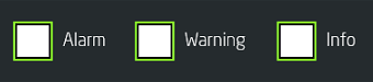 |
Allows you to filter the type of report to be displayed. |
Production report
The PRODUCTION REPORT page allows you to view the machine’s history, i.e. information relating to the welding cycles performed, along with the most relevant details for each individual cycle. You can scroll through the page using the touchscreen from right to left to view all the columns that make up the production report. You can also use the icons at the top of the page to set filters for the display.
Export
Option
This allows you to export the configured settings of the selected tool to an external USB drive. The button lights up when the USB drive is connected correctly. If the export is successful, a message on a green background appears in the top-right corner of the screen to confirm that the export has been completed.
Report Icons
| Icon | ACTION |
|---|---|
 |
Allows you to move to the next page. |
 |
Allows you to move to the previous page. |
 |
Allows you to export the production reports for the selected tools. |
 |
Allows you to refresh the reports on the machine. This operation is performed automatically when the page is opened. |
Select time range
| Icon | ACTION |
|---|---|
| |
DATE SELECTION: allows you to limit the time range of the list by specifying the start and end dates and times of the desired range. |
Tool selection
Using the drop-down menu it is possible to select the tool of interest from those stored, for which to view the production report.
Report information
After selecting the time interval of interest and, if necessary, the tool for which you want to view the report, the page will always display some information.
Graph
| ICON | ACTION |
|---|---|
 |
View graph allows you to view the graph of the welding cycle of the selected report item. |
Date/Time
Date and time of the processing cycle.
Result
Result of the welding performed during the processing cycle.
| ICON | WELD RESULT |
|---|---|
 |
GOOD: the welding has been performed correctly and the part is compliant. |
 |
REJECT: the welding has not been performed correctly and the part is non-compliant. |
Tool ID
Code assigned to the tool.
Name CEMAS
Code assigned to the CEMAS project for the tool.
Customer name
A specific name assigned to the tool by the customer.
Serial number
Sequential number of pieces produced.
Cycle time
Total duration of the processing cycle, expressed in seconds.
Welding time
Time taken to actually perform the welding, i.e. the phase in which the vibration is generated, expressed in s.
Deep
Total weld depth achieved, expressed in mm.
Welding start height
Position of the table at the start of welding, before the phase in which vibration is generated, expressed in mm.
Welding end position
Position of the table at the end of welding, at the end of the vibration phase and at the end of cooling, expressed in mm.
Icons
| Icon | ACTION |
|---|---|
 |
PARAMETERS NOT SAVED: indicates that the welding cycle has been performed without saving the changes to the parameters. |
 |
COMMISSIONING: indicates that the welding cycle was performed with the welding machine’s commissioning mode active. |
 |
CONFIGURATION: indicates that the welding cycle was performed with the welding machine’s configuration mode active. |
 |
DRY CYCLE: indicates that the welding cycle was performed under vacuum, without actually joining the parts. |